Fw 190D-13 "Yellow 10" construction page 2
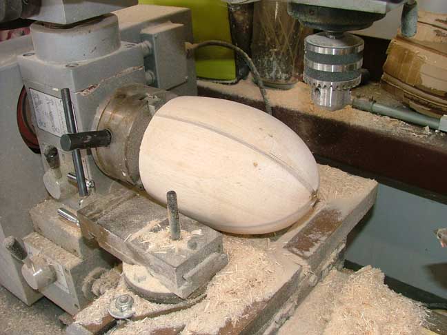


The next step in the construction of the Dora is the scratchbuilding of the spinner and cowling. I started with the spinner as it was relatively simple to make a plug and mold it. I cut 2 matching spinner profiles out of 1/4 ply and cut them so that they fit together like an "X". The 4 spaces between the ply plates were then filled in with balsa and a 1/2" wooden dowel glued to the centerline. The dowel was then chucked in to the lathe and the whole spinner was spun at high speed as I shaped the balsa to match the ply plates. Once I had the plug shaped, I fiberglassed it with 2 layers of 5oz cloth and sanded it on the lathe to keep it perfectly balanced and centered.
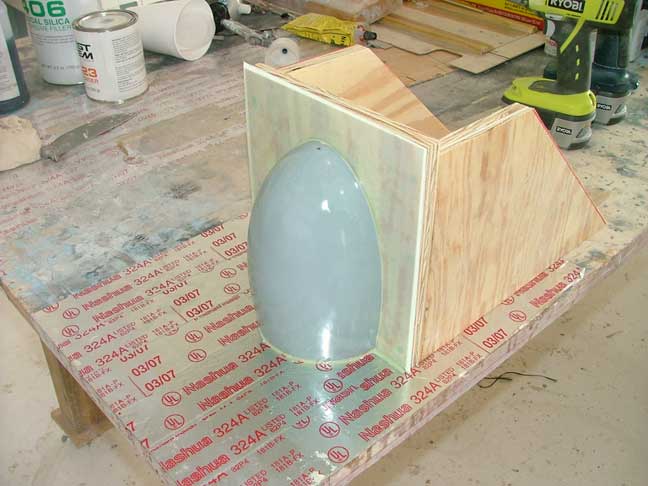


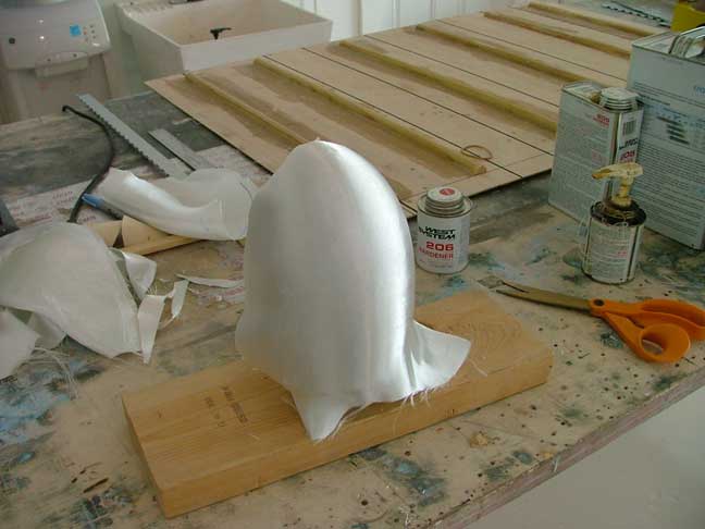
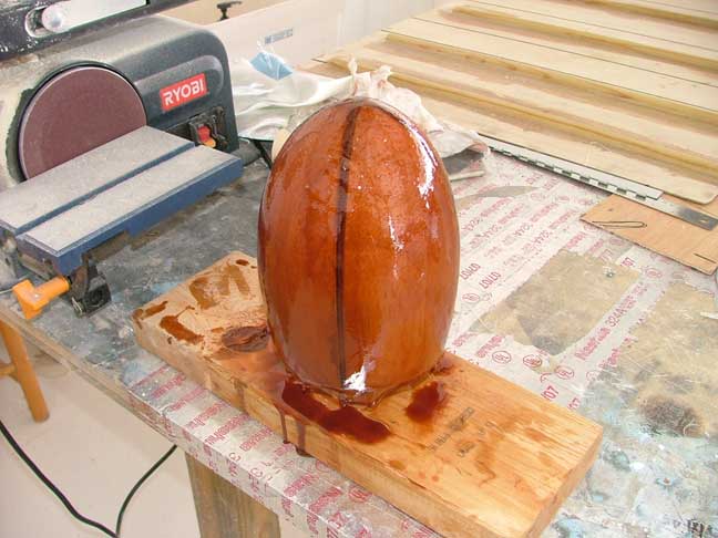
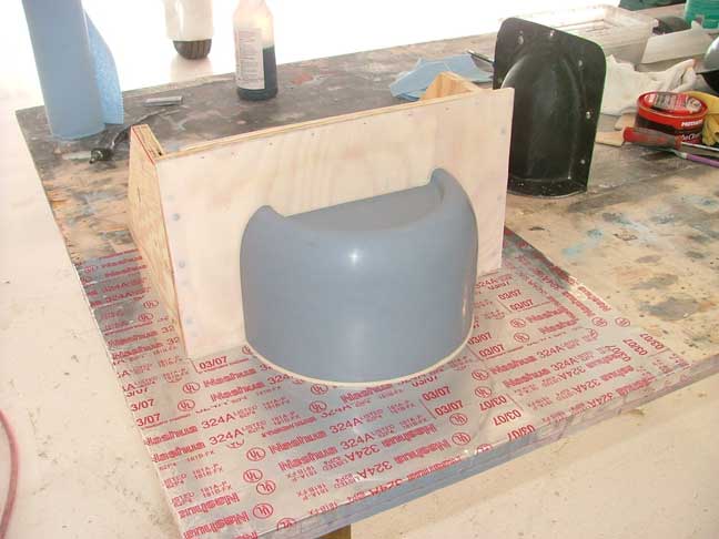
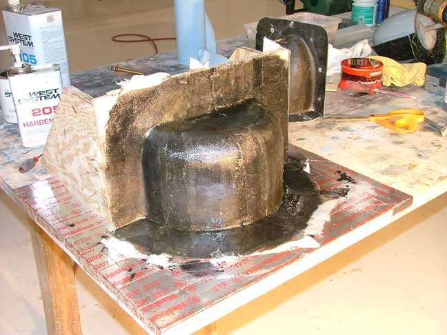
Once the plug was sanded smooth, it was primered and wetsanded all the way to 1000grit. A parting board was made from ply, faced with mylar and positioned on the center of the plug which was waxed and coated with mold release. Thick resin was used for the corners and multiple layers of glass cloth were applied. Once cured, the parting board was removed and the other side was done in the same manner. This produced a 2 piece mold of the spinner. I used some black graphite powder in the resin as the dark color makes spotting air bubbles easier.

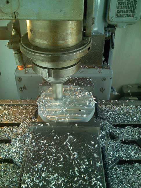
After the mold had cured for a week, I applied mold release to the inside and laid up a spinner from carbon fiber. I also machined back plate from 1" aluminum plate. The spinner is held to the backplate with 10 countersunk allen head 6-32 screws. 2 other spinners were made in the same manner, one for a 3 bladed flying prop and another for static display.
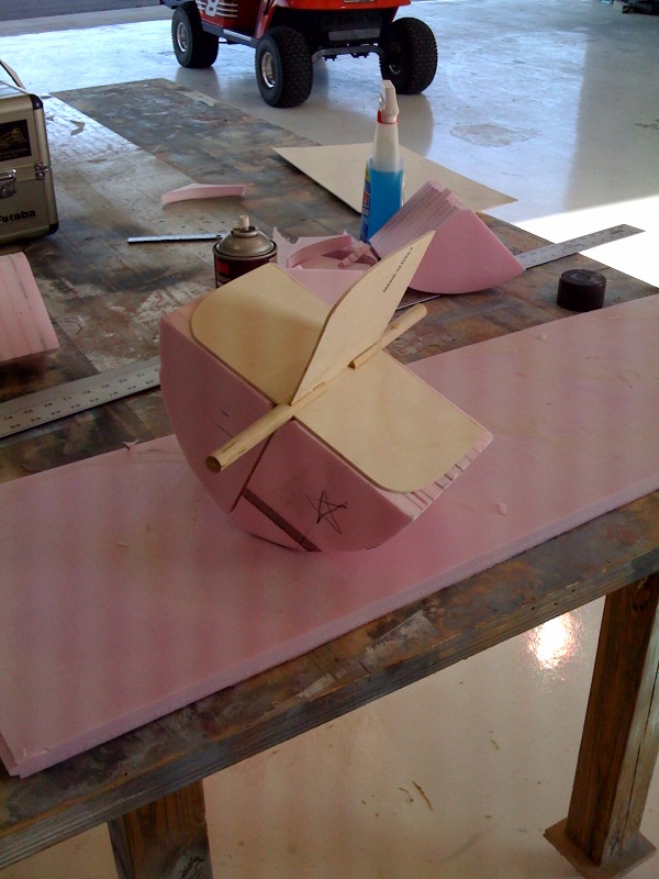

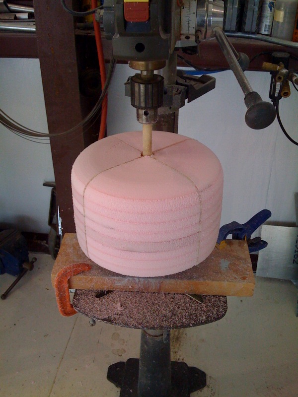
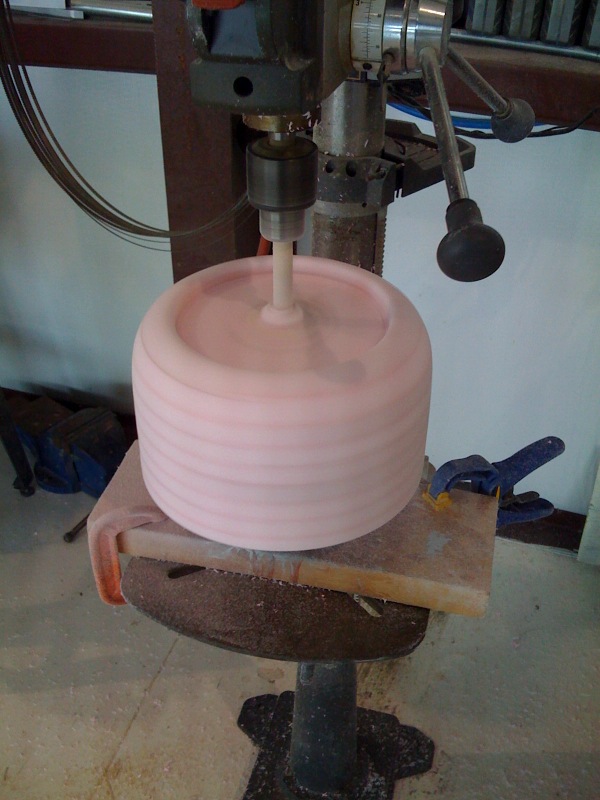
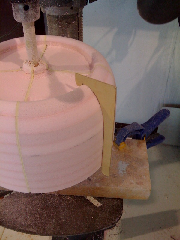
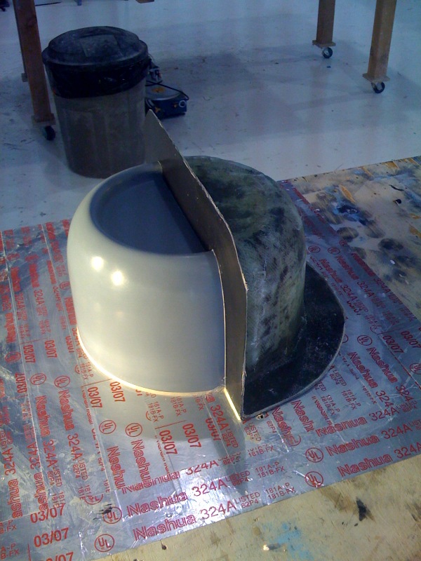
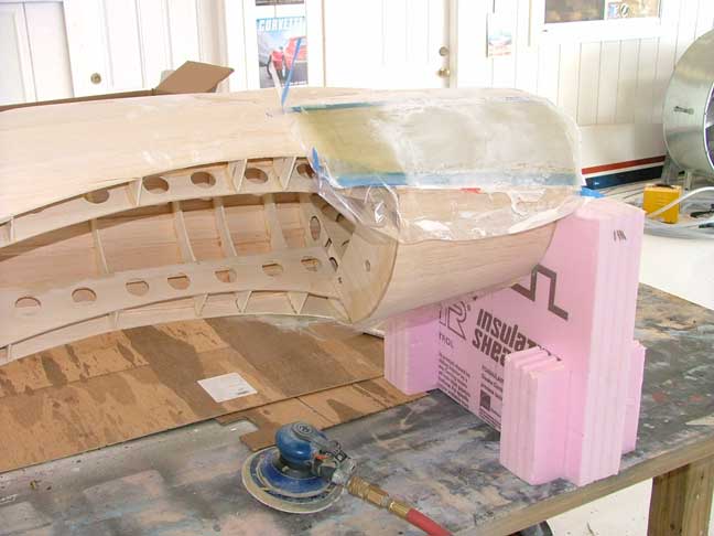
Next it was time for the cowling. The cowl was made in a similar manner to the spinner but this time out of pink foam. I did the same ply cowl outline and filled in the open spaced with pink foam. It was spun on the drill press and shaped with various sanding tools to get the correct shape. A ply template was used to check the finished shape.

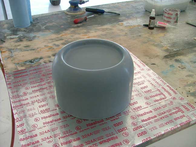
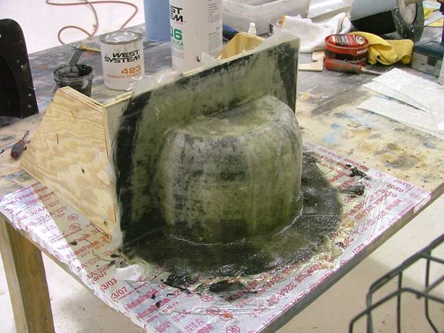
The cowl plug was then glassed, primered and wetsanded to 1000 grit before the same process as used on the spinner was started again.
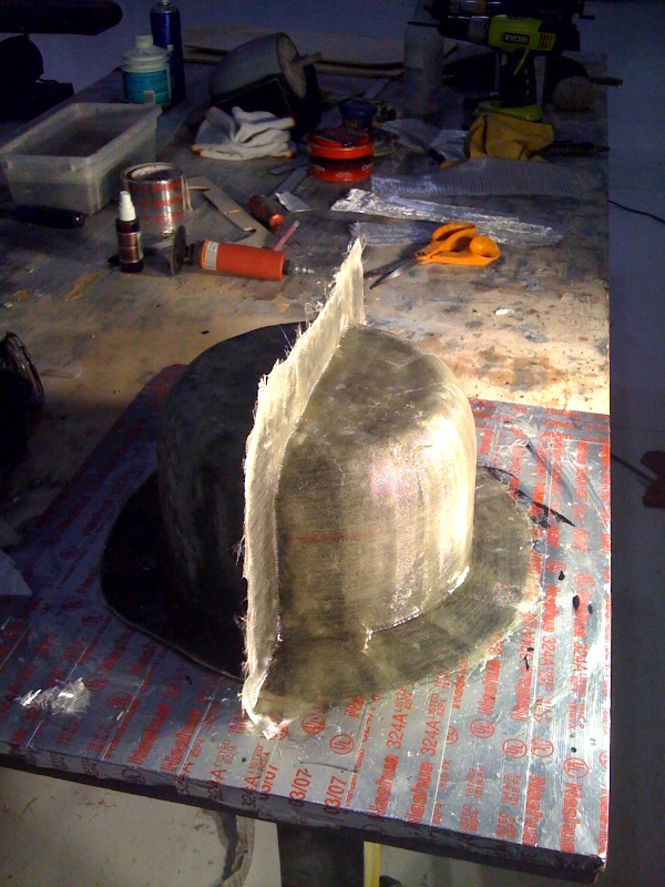
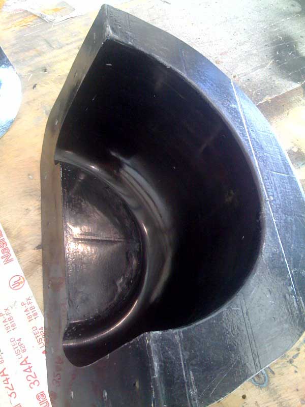
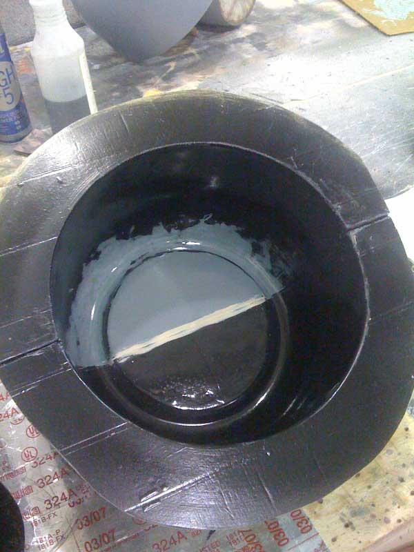
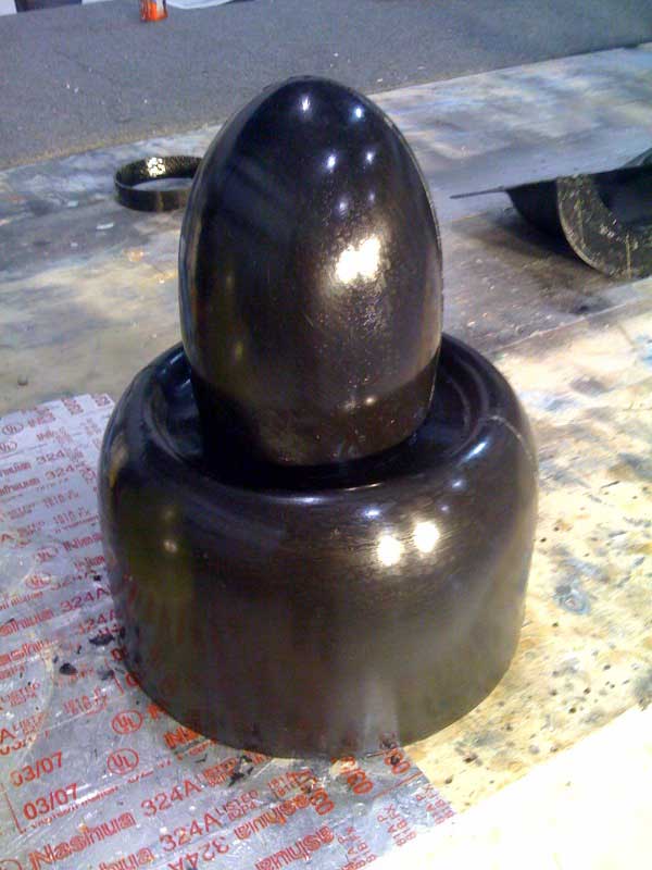
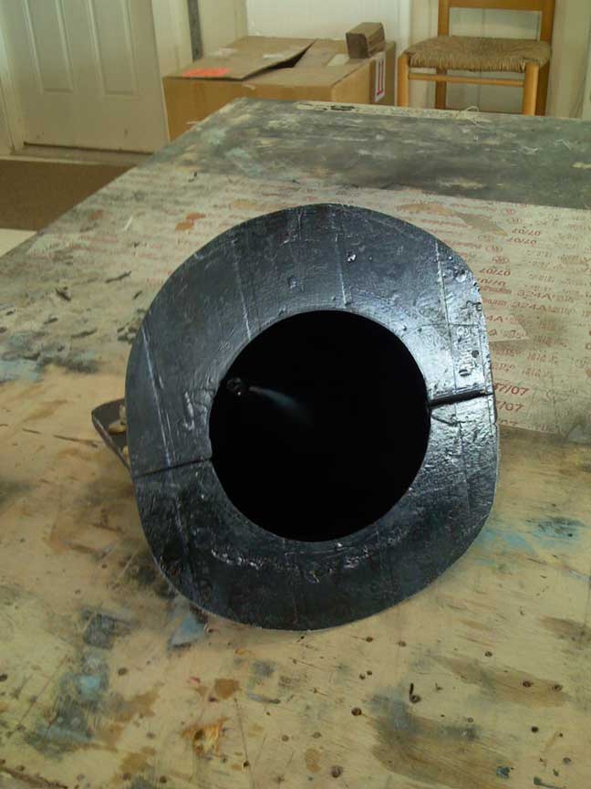
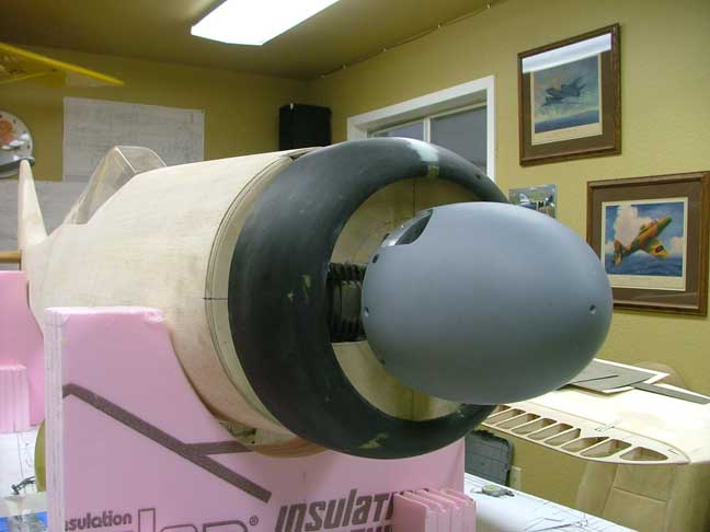
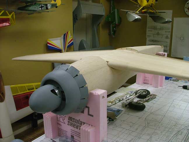
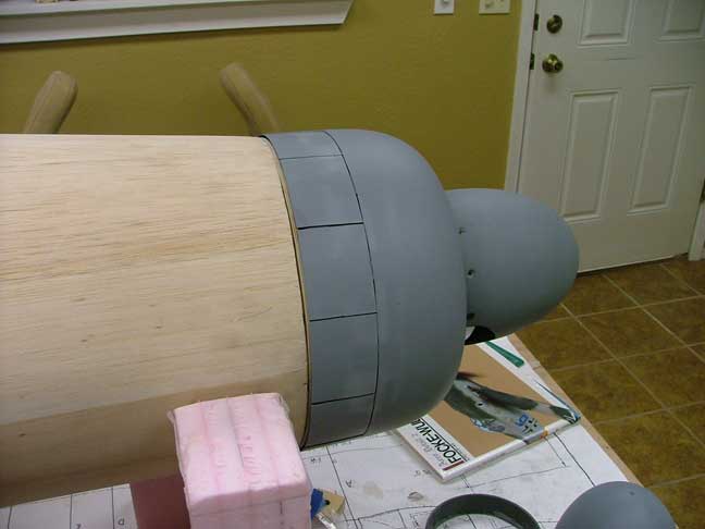
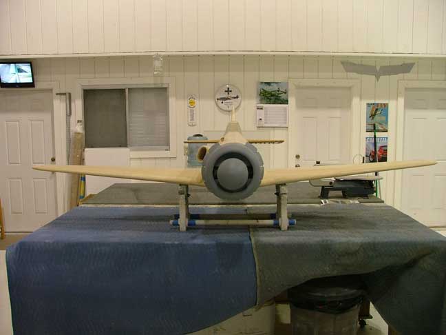
Once the first side cured, the process was continued on the other half of the mold. Once cured, I laid up a cowling with fiberglass cloth and a layer of black gelcoat resin. Basic cowling and spinner now complete.
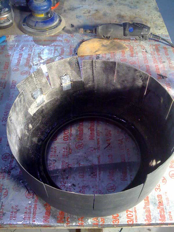
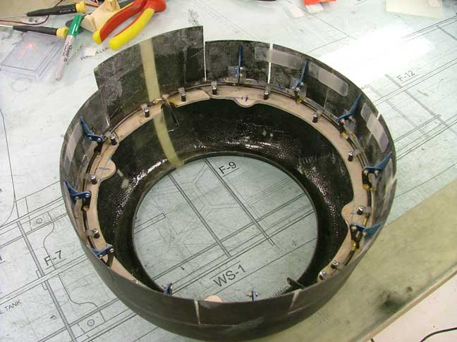
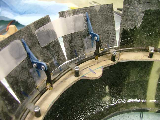
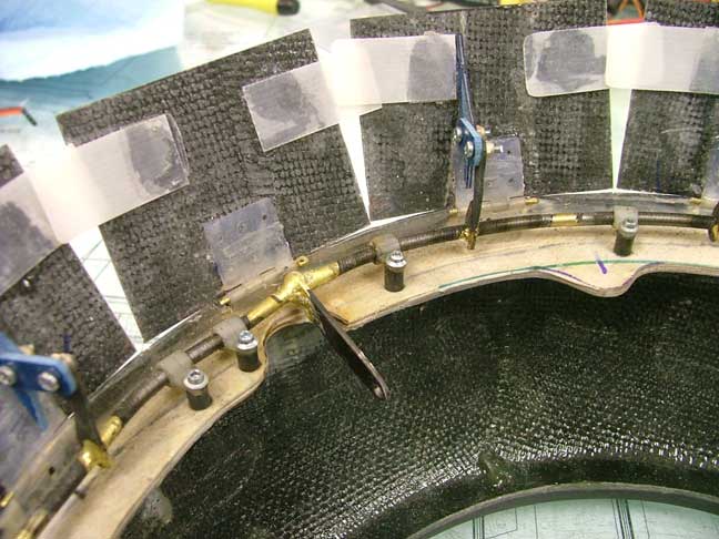
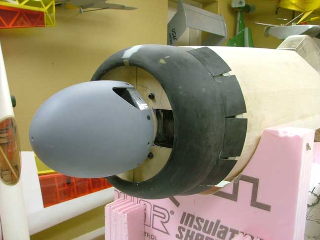
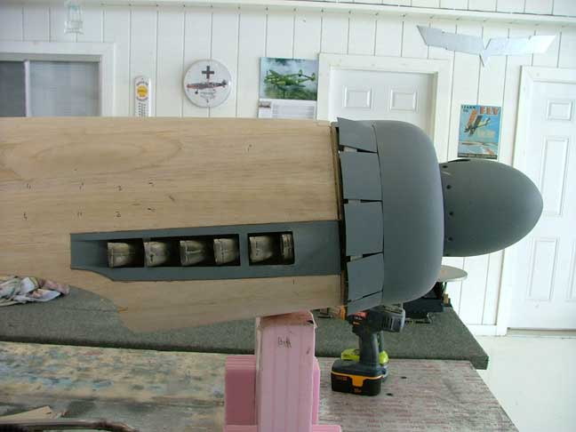
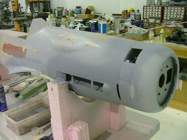
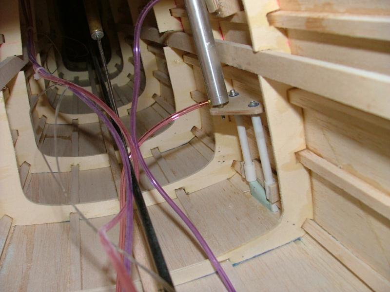
Slots were then cut into the cowling with the intention of making the cowl flaps movable and servo operated. The individual cowl flap segments were cut free from the cowling and hinged with dubro flat hinges. A 1/8 ply ring was then epoxied to the inside of the cowling. A snake drive made from R/C boat flex drives was then positioned around the ply ring and held in place with nylon keepers. Small steel arms are brazed to the ring and actuate the flaps. When the ring is twisted or spun in its mounts, the arms move outward and open the cowl flaps.
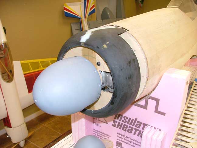
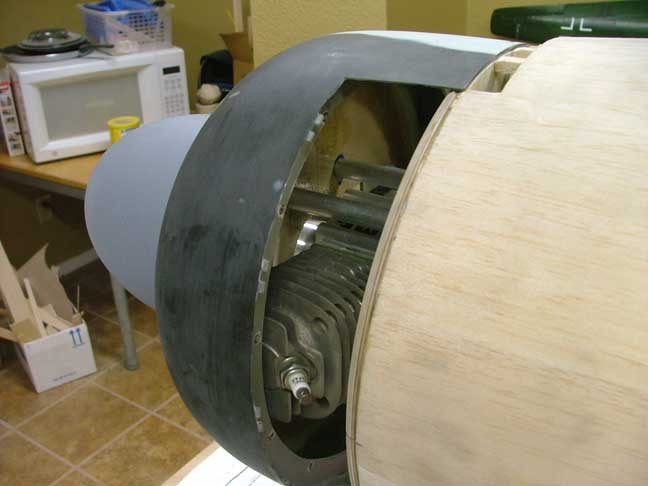
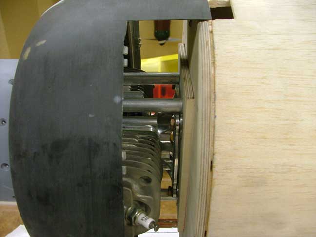
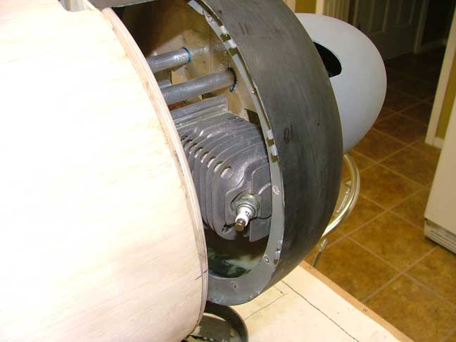
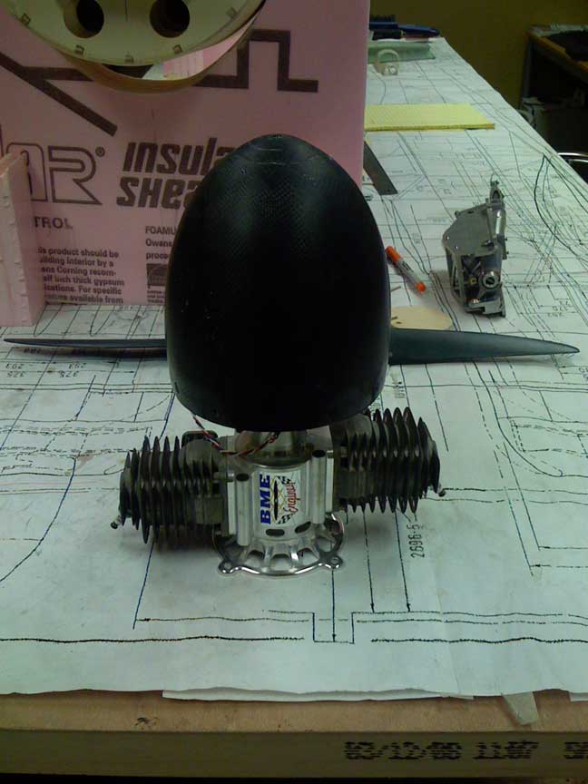
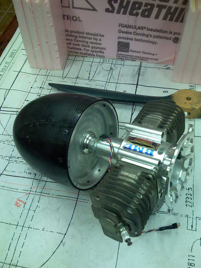
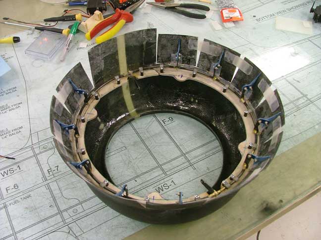
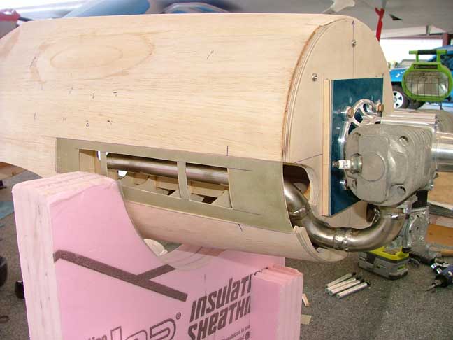
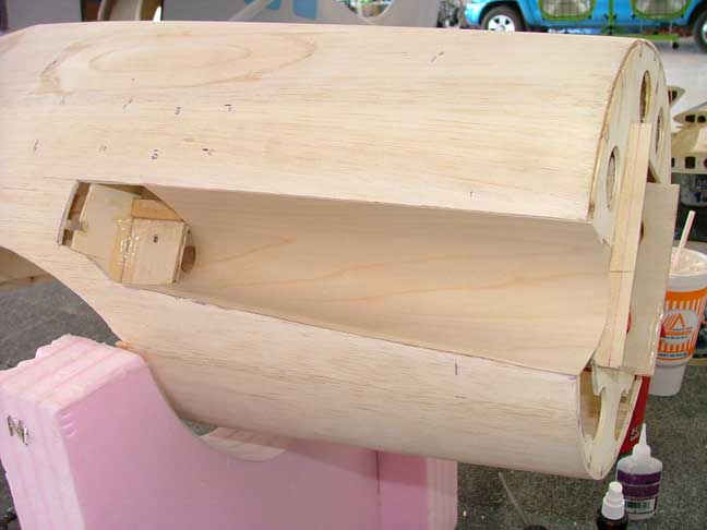
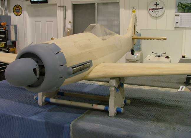
I made a firewall from 2 layers of 1/4 ply and mounted the BME 110 twin with 2 deg of right thrust. A 1/8 ply baffle plate was then epoxied into the cowling. The baffle plate provides cooling air for the cylinder heads and gives a location for mouting the cowling to the firewall without interfering with the cowl flaps. Standoffs made from 1/2" aluminum rod solidly mount the cowling to the firewall. The bolts for the standoffs will be inside the spinner cone so they wont show in the planned radiator mock up.
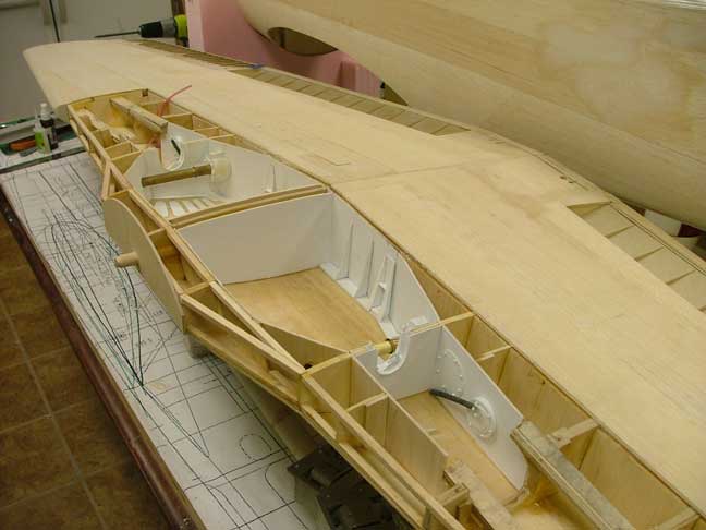

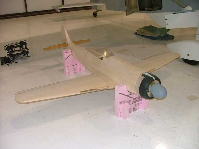
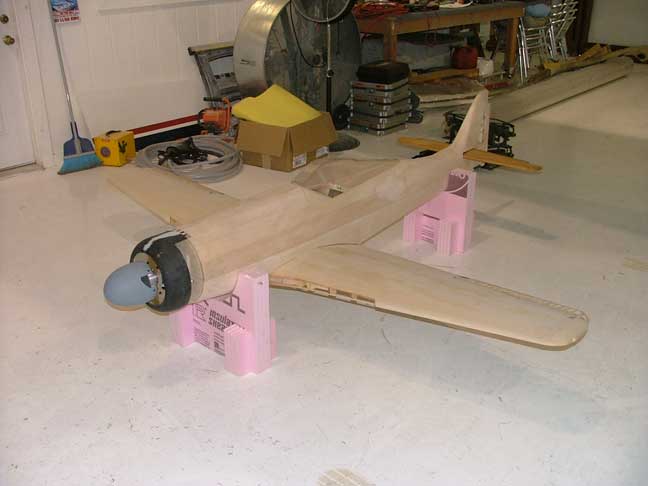
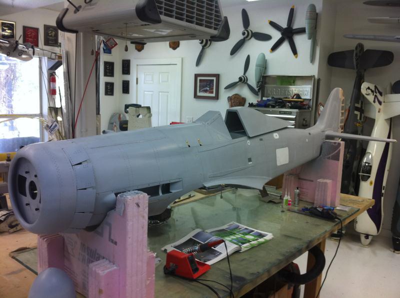
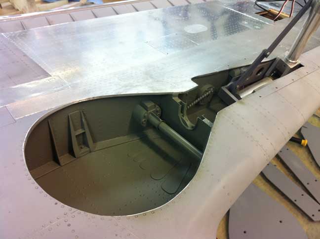
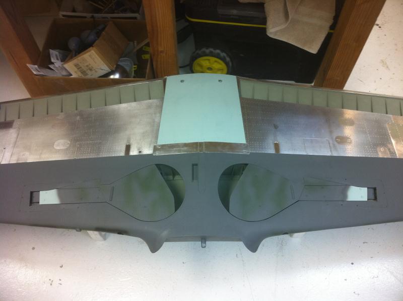
The other wheel well was finished detailed with styrene plastic and both wells were painted RLM 02. I also took a minute to put the model together for a few inspirational or motivational pics.


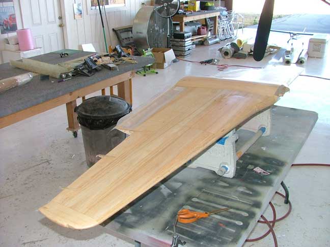
2 futaba 9206 servos are mounted to the rear of the baffle plate and actuate the cowl flap drive ring. I also finished sheeting the wing bottom and leading edge.
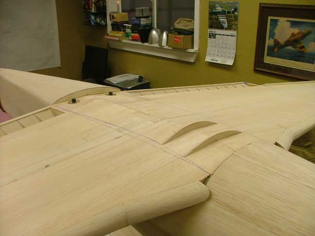
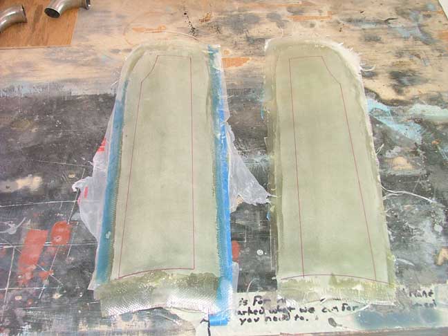
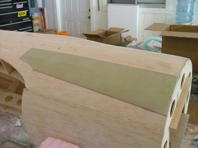
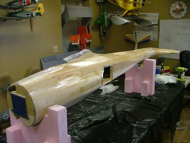
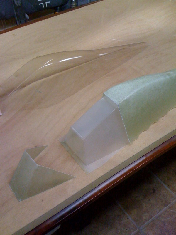
Next the wing was mounted to the fuselage and the belly pan was fabricated from balsa ribs and sheeting. Following this, the wing was glassed with 1.4 oz cloth and set aside to cure. I also made some fiberglass panels to cover the exhaust area by glassing over monokote that was ironed down to the front fuselage area. Once cured, the glass was popped off and sanded to shape.


The stub was then cleaned on the wire wheel and 11 more were made just like it.
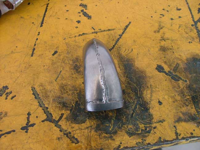

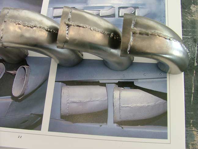
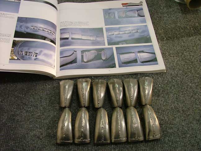
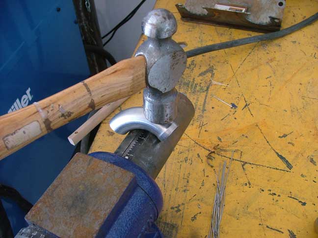
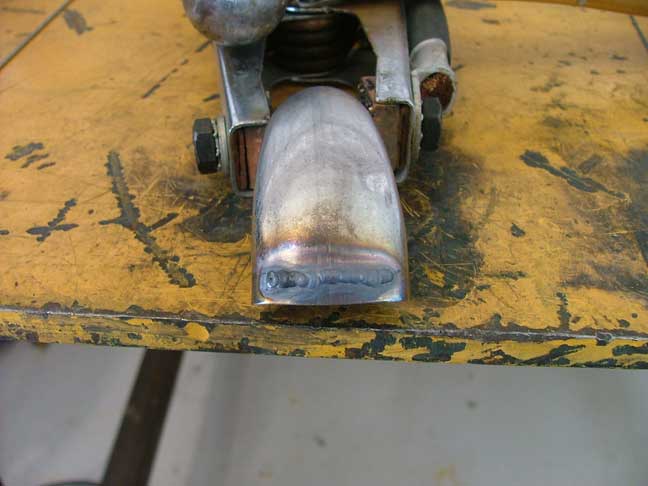
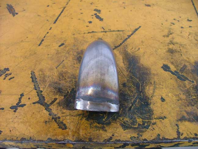
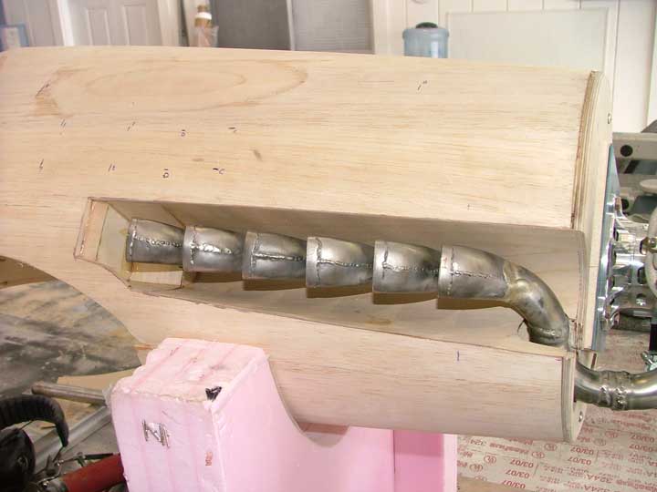
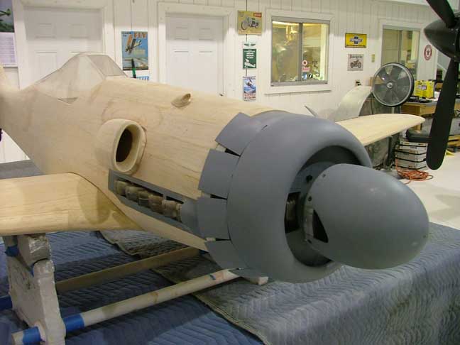
One of the things Ive always wanted to do is a live exhaust system. I started by hammer-forming some stainless exhaust elbows from K&S exhaust. Once shaped, I TIG welded several beads onto the end of the exhaust stub, then ground them down to get the flat flange shown. I then welded a bead running down the center of the exhaust stub just like the full size.


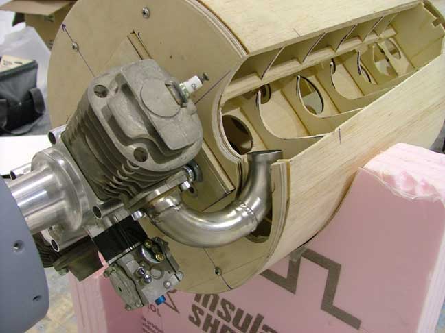

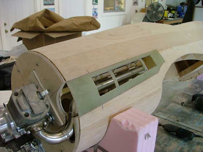
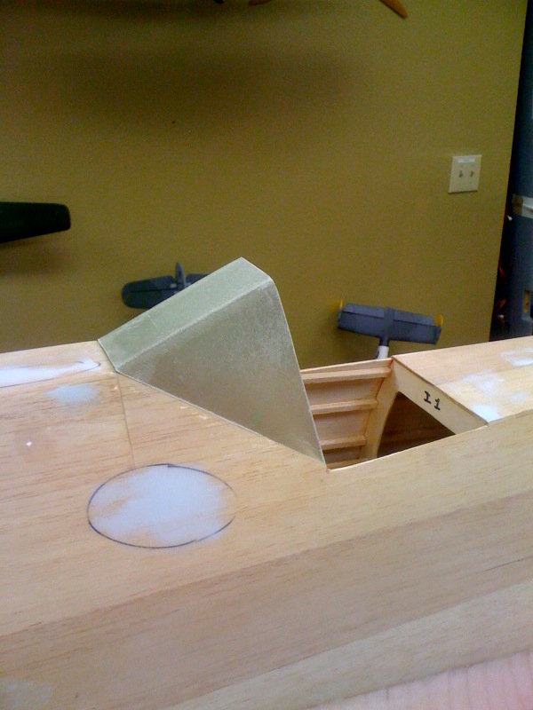
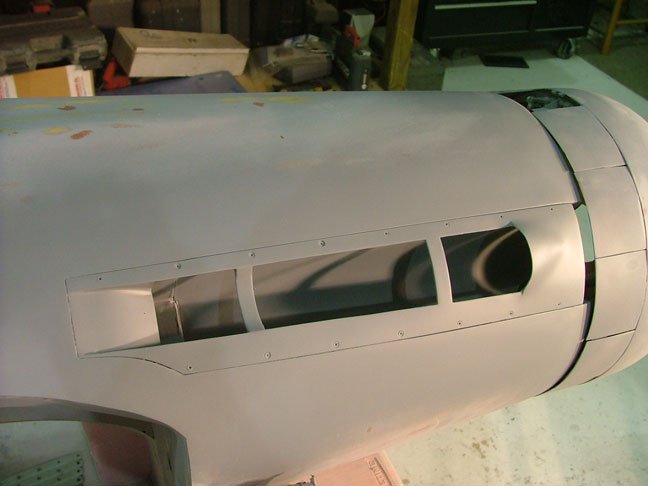
The exhaust areas were then removed from the fuselage and more stainless elbows were welded to the flange on the cylinder head and continue to a manifold inside the fuselage. I also cut the holes in the fiberglass covers to match the full size and shaped them to fit in the exhaust area.
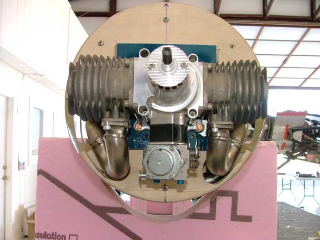
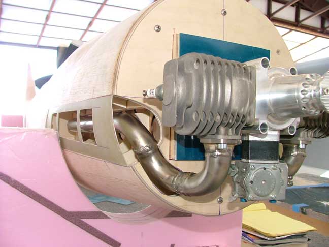
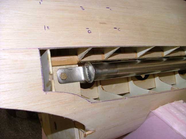
The other side was finished in the same fashion. Small stainless tabs were welded onto the end of the manifolds and bolted to the wing saddle to support the rear end. I then sheeted the exhaust area with thin 1/32 ply. The individual exhaust stubs will be welded to the manifold 6 to a side and be fully functional.
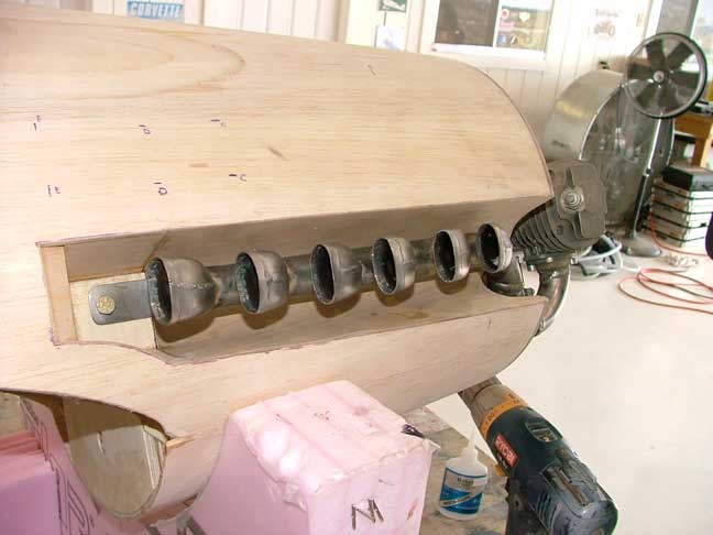
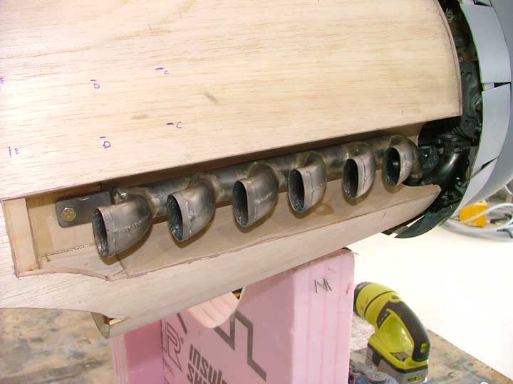

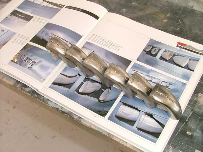
The stubs were saddle cut and brazed onto the manifold. I tack welded all 6 into position and then brazed them all at once. I then sandblasted the entire assembly to remove the flux from the brazing process.

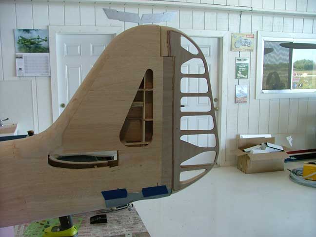

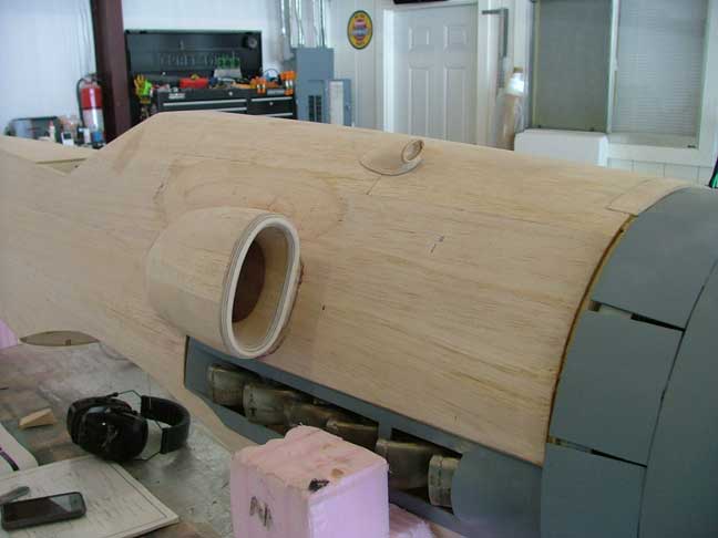
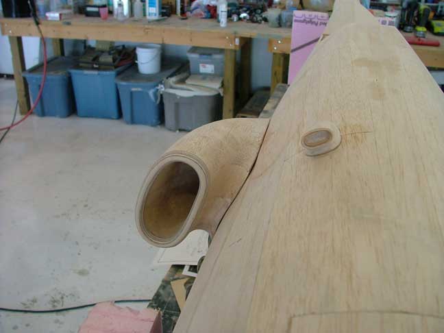
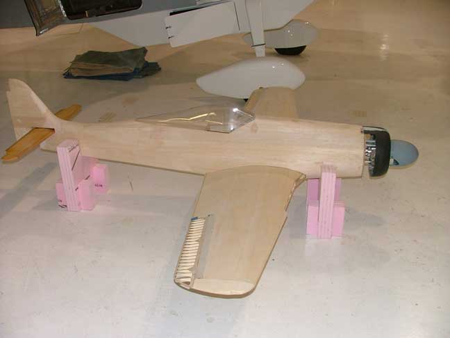
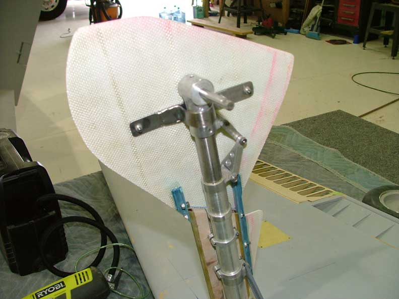
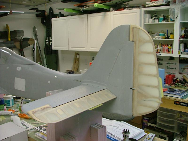
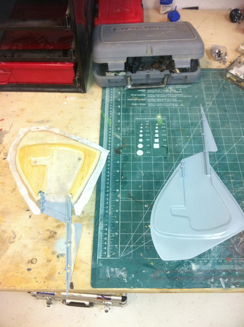
The rudder was constructed in the same fashion as the elevators and ailerons. 4 robart hinge points hold it in place. The Intake scoops were carved from balsa blocks. Plywood rings on the intake lip give some ding resistance. The scoops will be glassed seperately and attached later on.

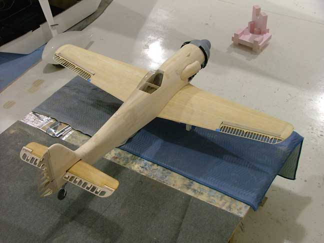
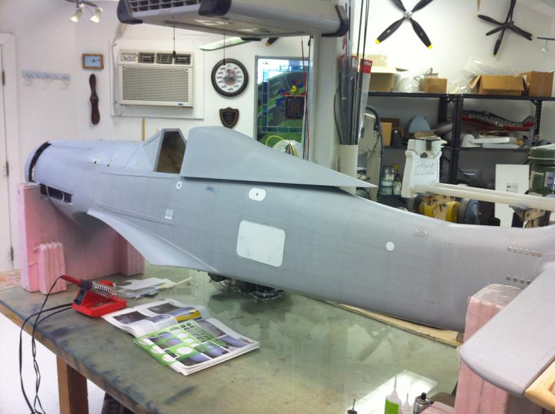
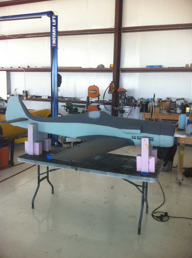
More put together motivational pics. Now on to wing fillets and then time to start glassing, priming filling and sanding.

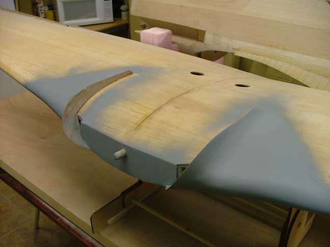
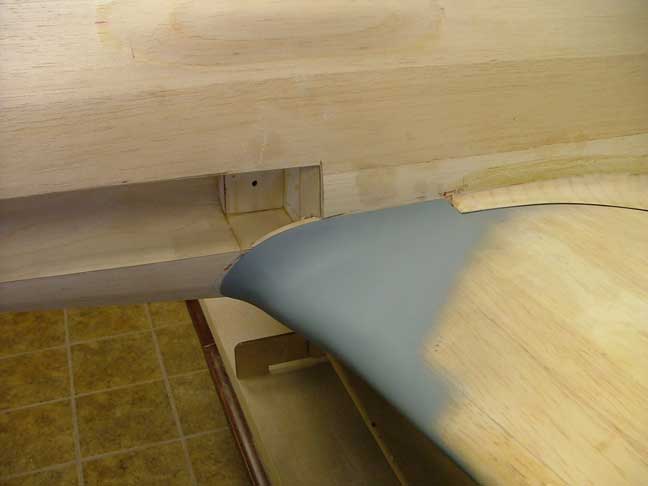
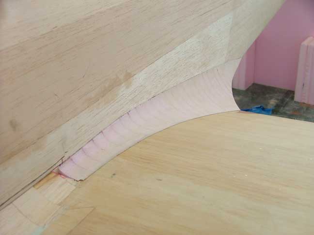
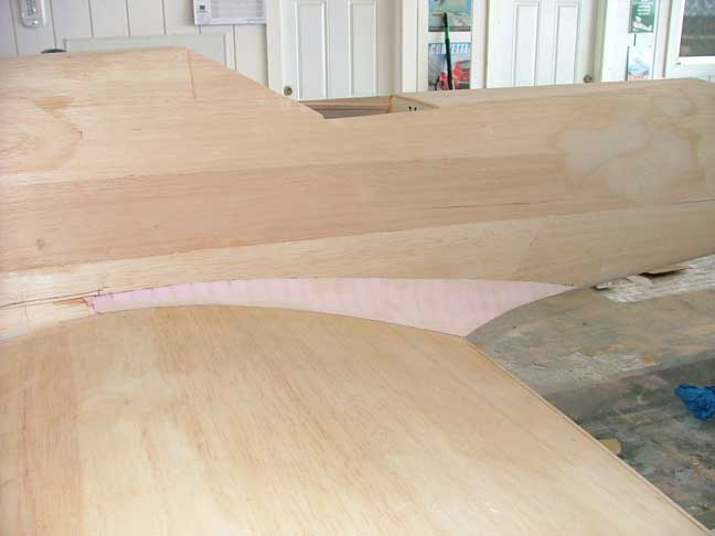
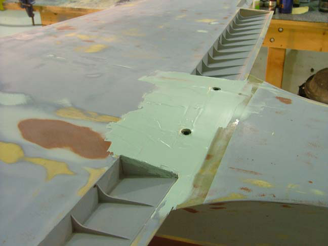
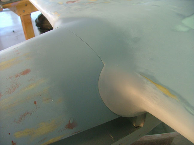
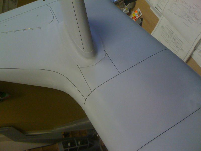
The front wing fillet was built up from balsa and attached to the wing as per the full size. The rear fillet is made from pink foam and attached to the fuselage and glassed.
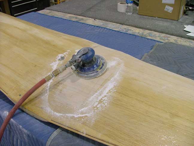

The fuselage was then glassed with 1.4 oz cloth and sanded out along with the wing. I use a regular palm DA sander with 180 grit to sand the flow coat of resin. I also glassed a canopy to fabricate the front windshield which was permanently attached to the fuselage.
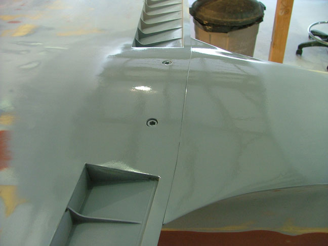
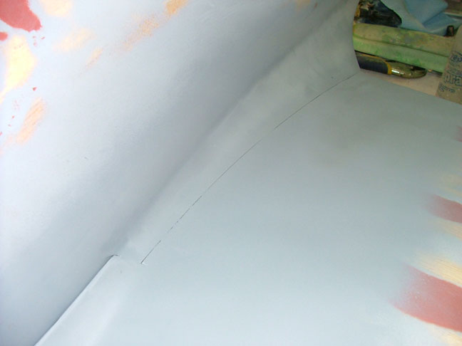
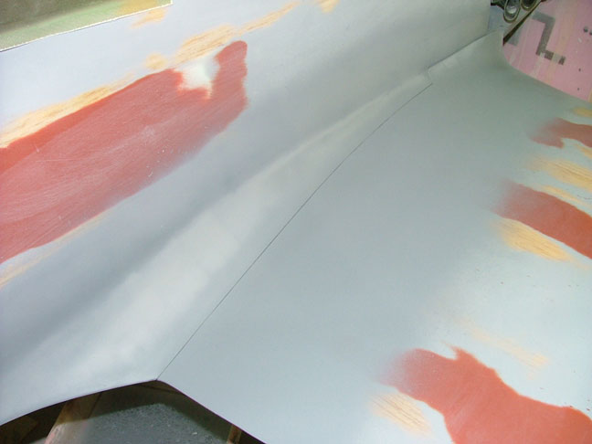
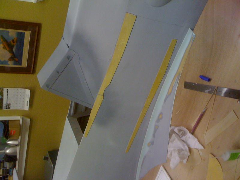
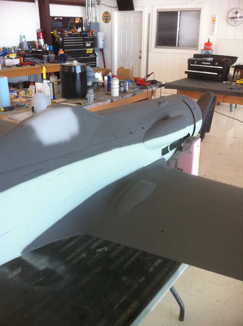
After sanding out the first primer coat, I used some evercoat and brown packing tape to get a fine seperation line between the wing and fuselage.
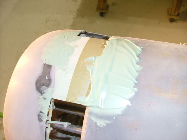
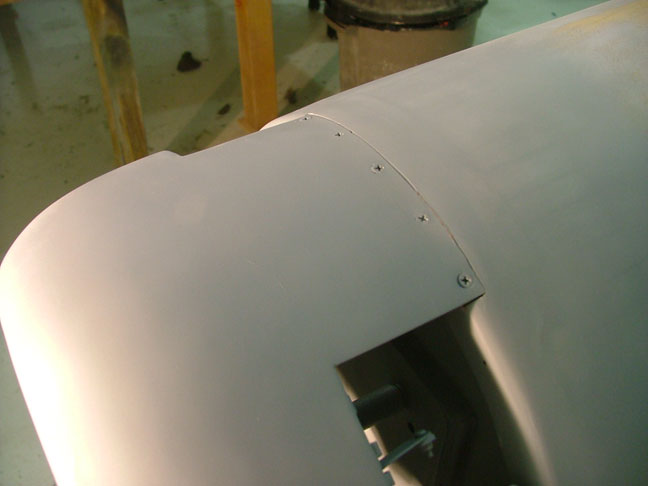

The cowling to fuse juntion was also smoothed out and the exhaust covers were mounted to the fuse with countersunk screws.


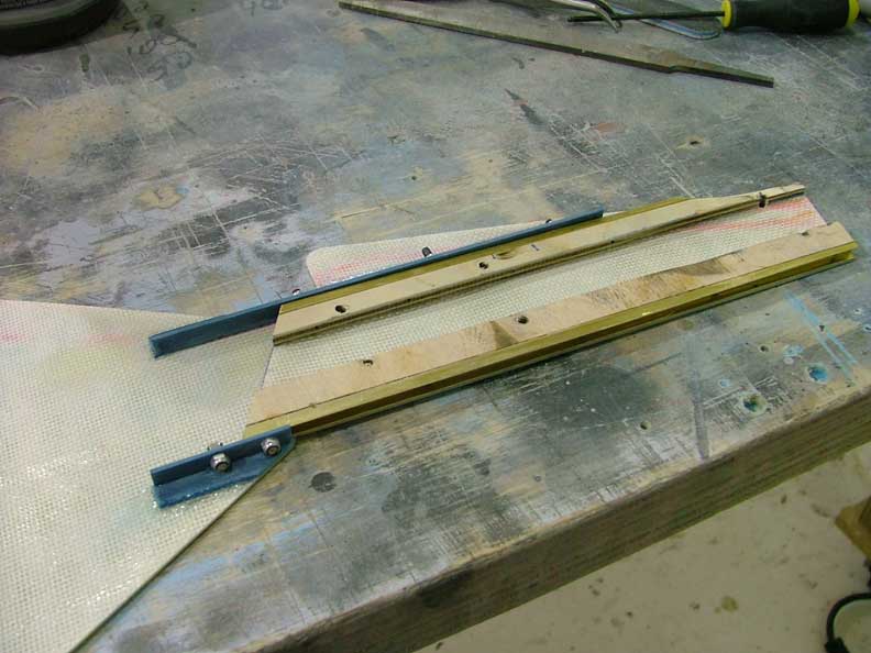
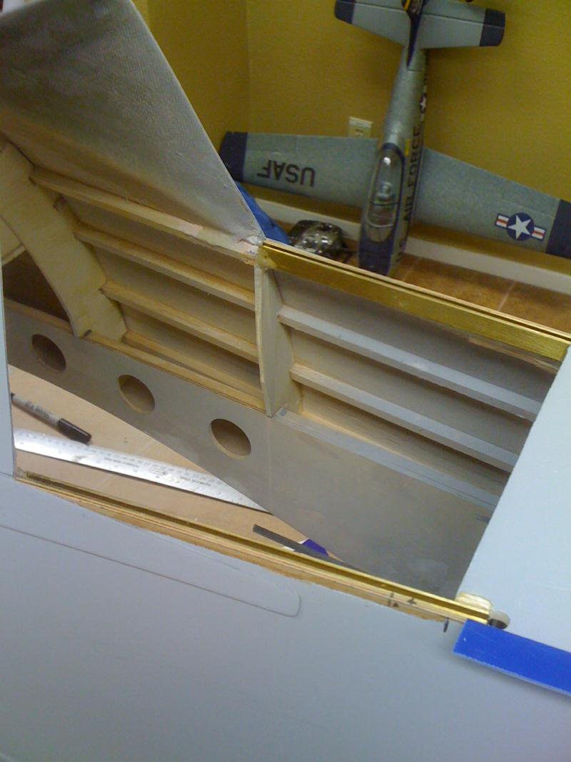
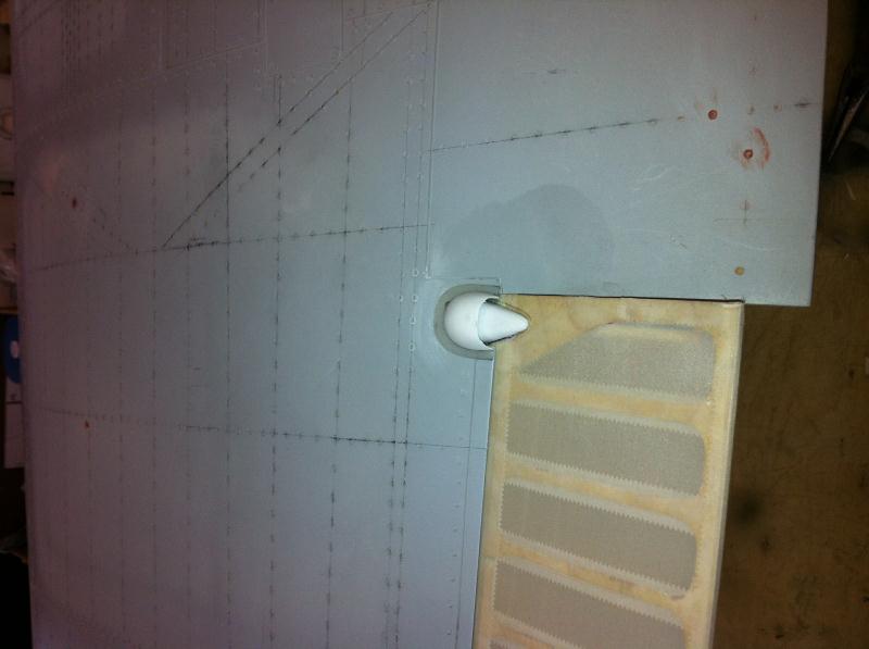
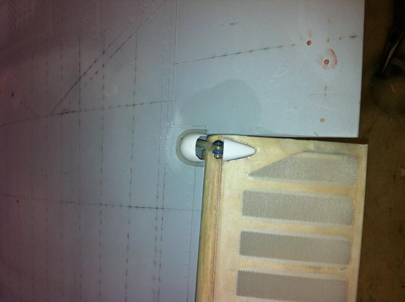
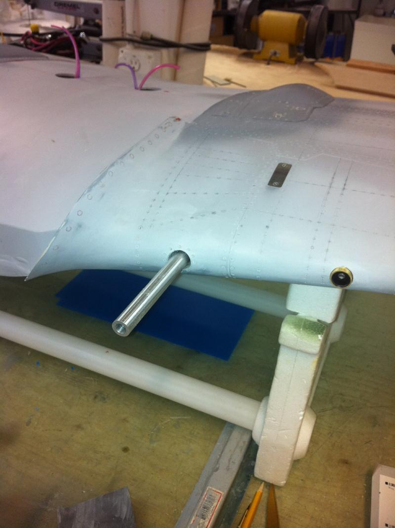
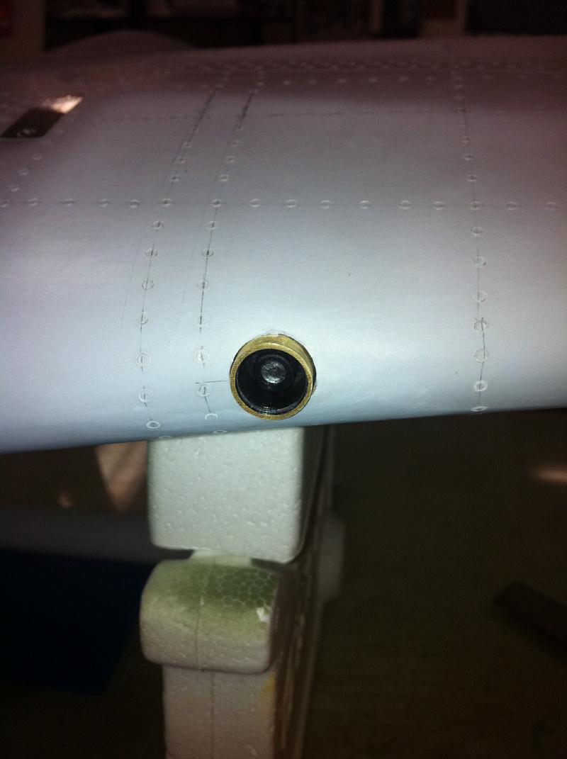
Landing gear doors are made the same as on the SisT 1/5th scale 190s. The upper door has brass channels and the lower door has small socket head screws that ride in the channels allowing the door to slide up and down when the oleo compresses.


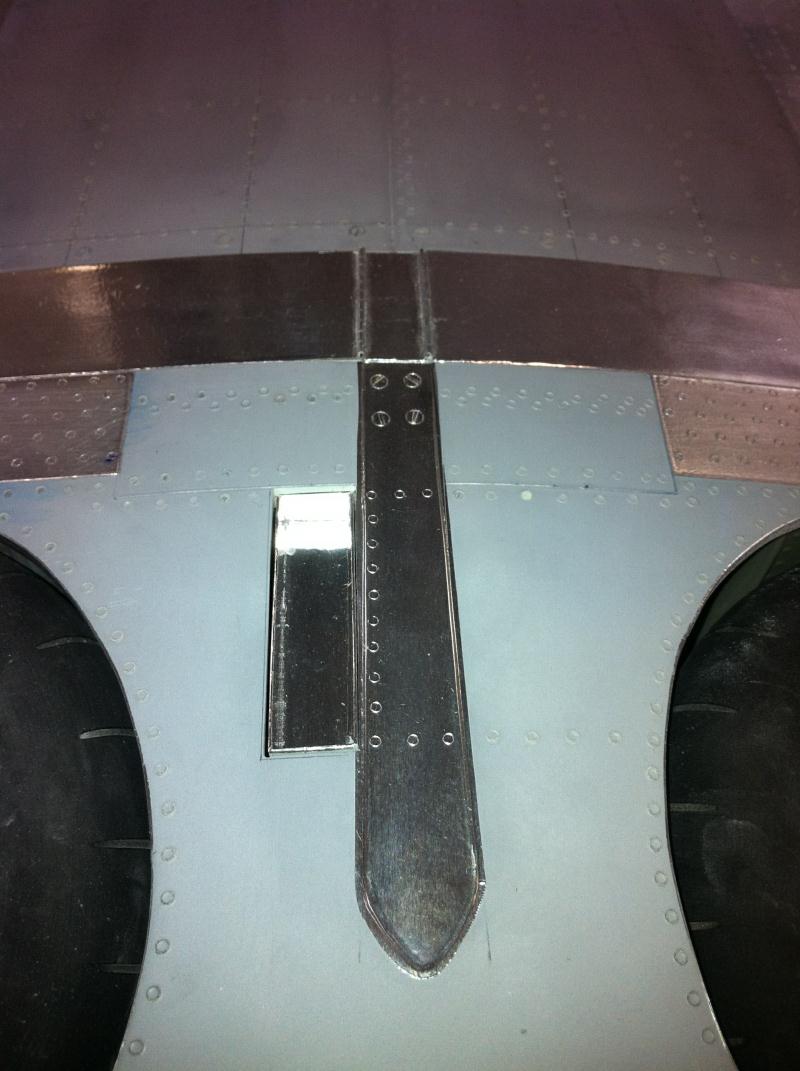
Fuselage strengthening strips made from ply and fliteskin. Also, sliding canopy works just like the SisT 190s. A single 4" stroke cylinder will operate the canopy.

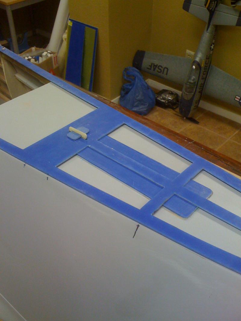
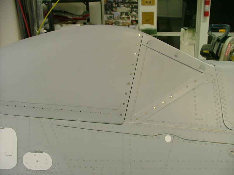
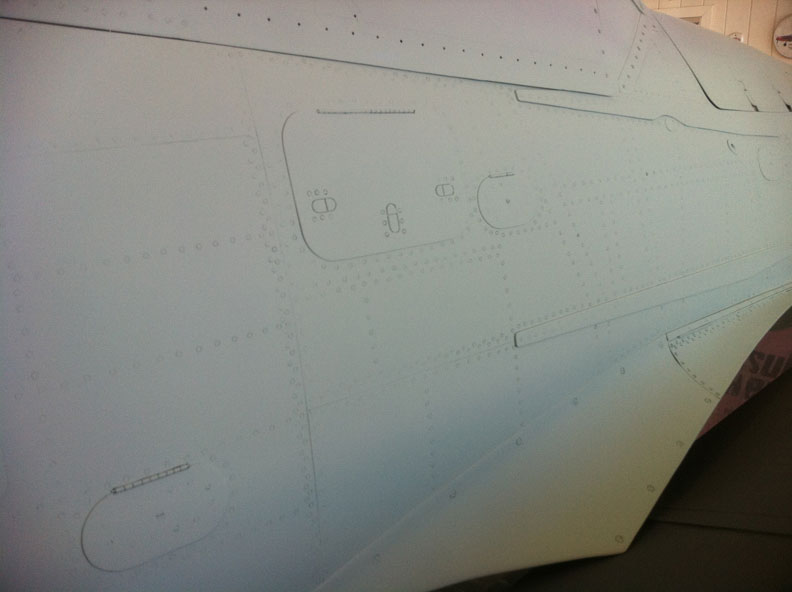
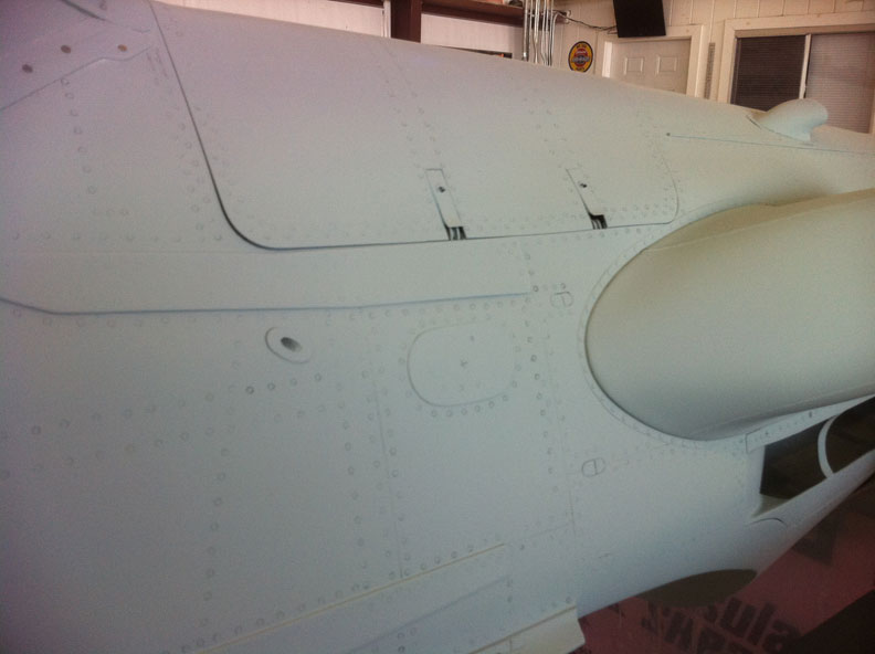
Fuselage detailing starting with panel lines using chartpak tape and primer, then lots and lots and lots of rivets, followed by styrene and brass details. The tail surfaces were then covered in solartex with pinked rib tapes and simulated rib stitching. Trim tabs from fliteskin.
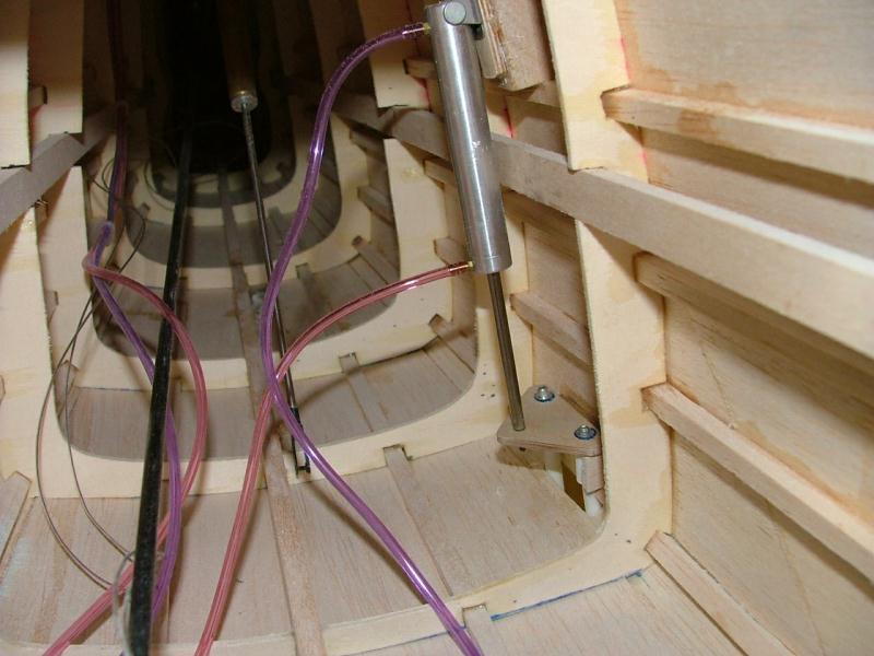

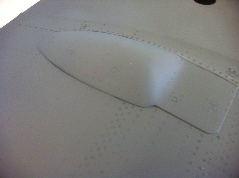
Pilot's step is operational with an air cylinder that will work with the canopy. Canopy details reproduced with miniature countersunk screws. The wing cannon blisters were shaped from foam and glassed, then affixed to the wing.


Lots more rivets on the wing. I used plunge moulding to make the small aileron pushrod fairing. The ailerons were also covered in solartex with the same pinking tape and rib stitching.
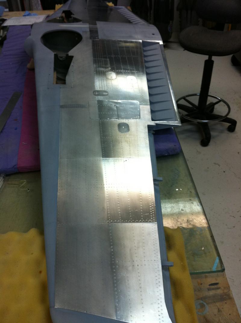
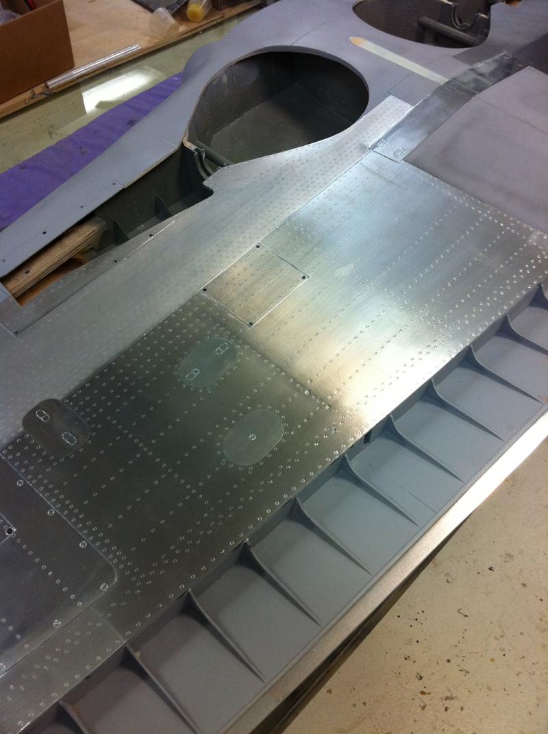

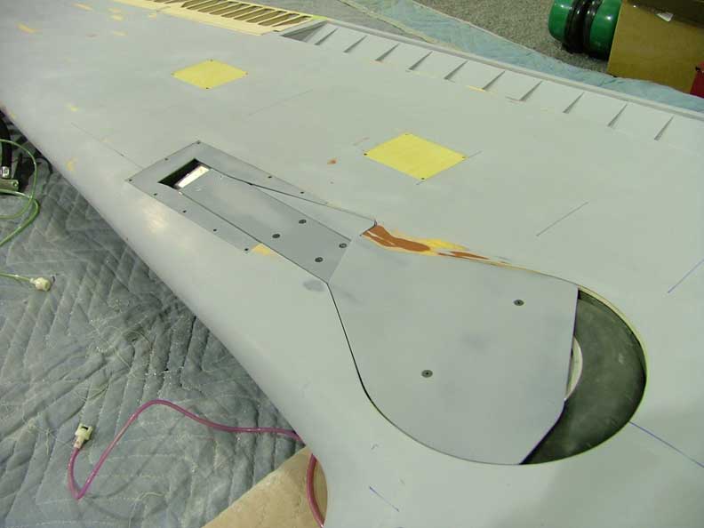
The bottom of the wing was covered in Aero foil from Meister scale. It was then riveted. The gear doors were also given some interior detail with balsa glassed on. Pitot tube made from carbon pushrod and cannon barrels machined on the lathe from aluminum rod. The combat camera was also replicated with some brass tube and plastic.
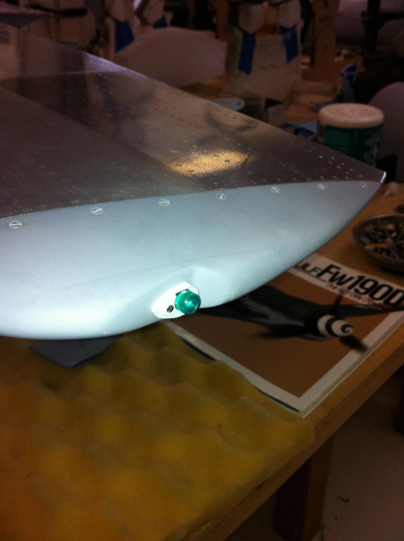

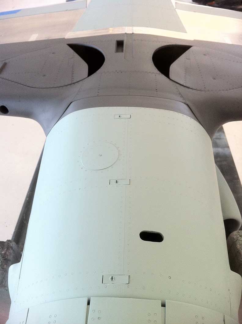
Close up of the combat camera. The 30mm shell ejection chute was made from styrene and aerofoiled. The wing tip lights are operational and have some small styrene details. Wheel wells were tidied up and lower fuselage details installed. Now time for paint!


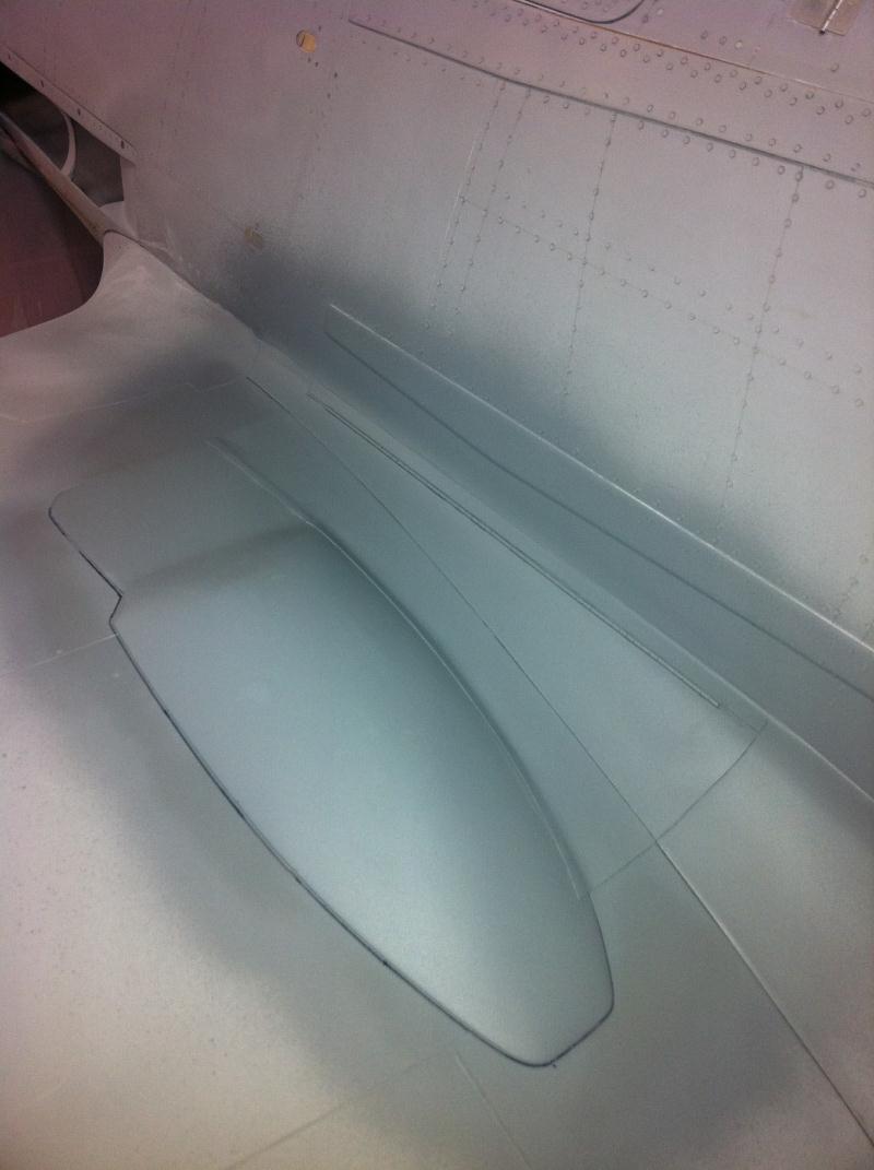
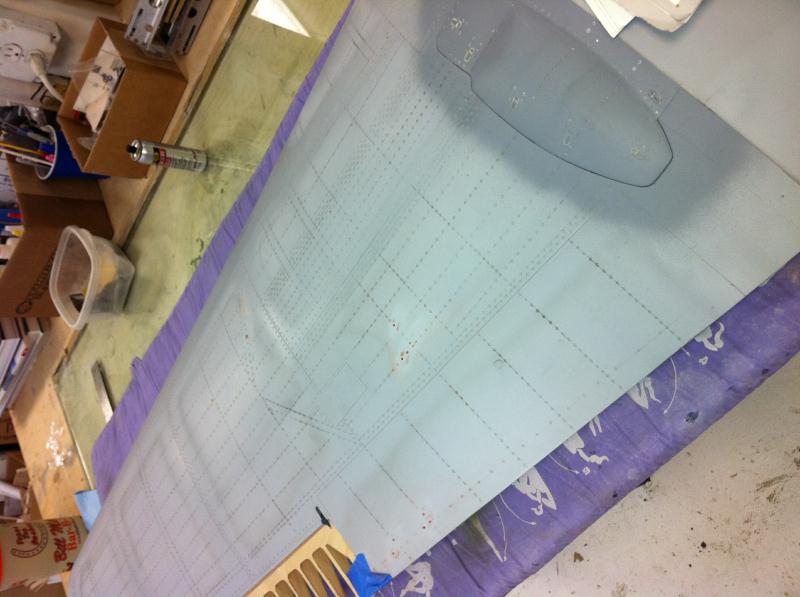
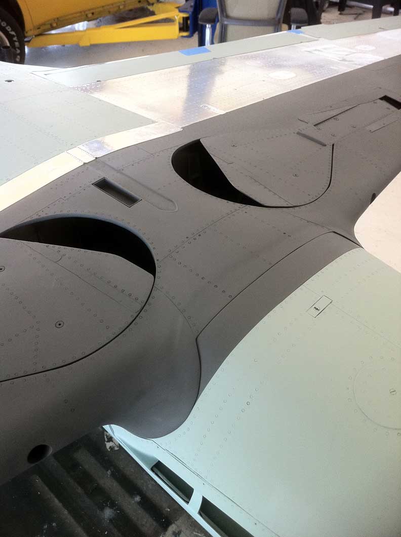
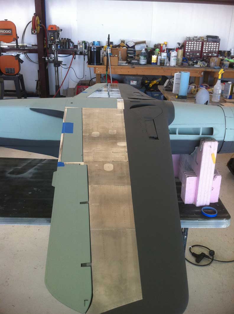
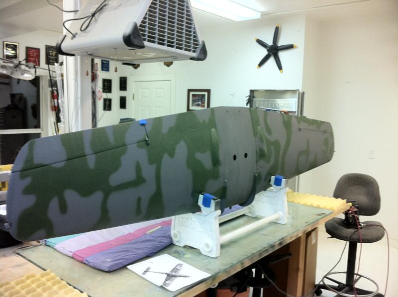
PAINT! Finally after 7 years its time to paint. Here are some shots of the fuselage and wings in base coat of RLM 75 and RLM 76 light blue


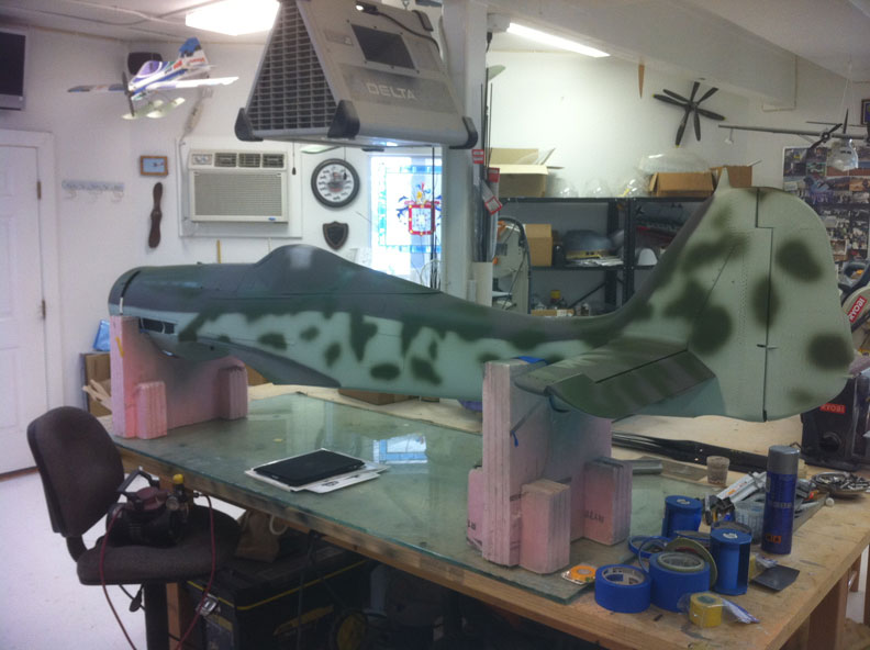

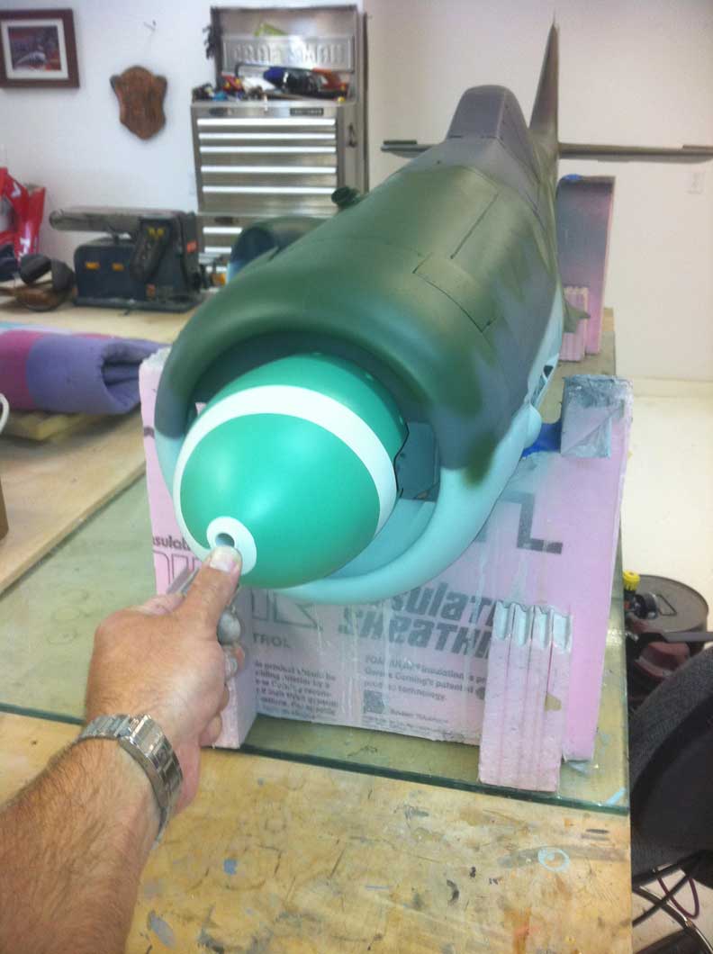
Once the base coats were done, I started mottling the fuselage with RLM 83 bright green. I also did the spiral on the spinner with scale white and RLM 25 Green.
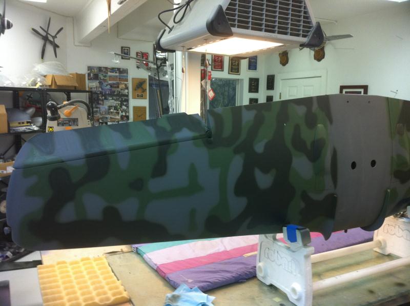

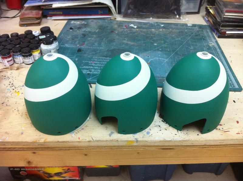
The wing camo was done freehand with the airbrush just like the fuselage. I made 3 spinners, one for a two blade flying, one for 3 blade flying and another for static display. The wing underside was also painted to match the documentation.