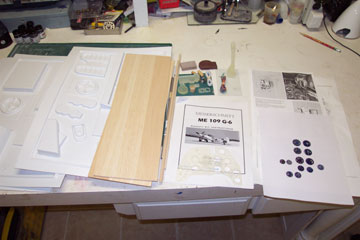
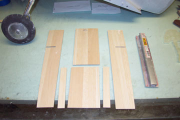
Here are all the components of the PCM models Bf-109 cockpit kit.
First step is to make the floor sections from 1/8 balsa.
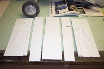
The balsa floor sections are then laminated with .030 white abs plastic sheet and the preformed side panels are cut to shape.
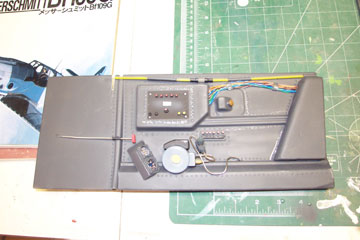
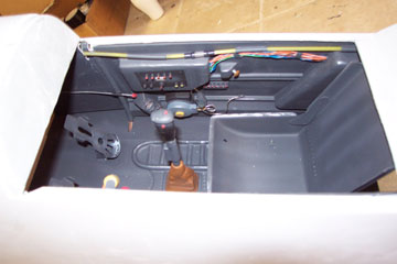
Left cockpit side panel after several hours work. The color is German Panzer grey which closely approximates RLM 66 cockpit interior color.
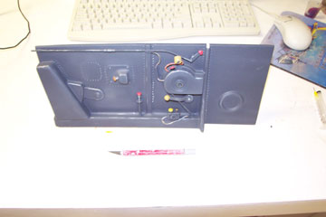
This is one large cockpit .
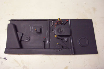
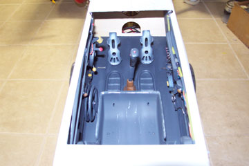
Right side of cockpit. Visible is the circuit panel, radio knobs and oxygen supply with guages, fuel line for drop tank and interior wiring.
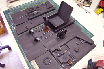
Completed cockpit panels. PCM's cockpit kit is impressive, everything you need to build what you see here is included in the kit.
All of the cockpit painting/weathering was done with a Paasche double action airbrush and an airbrush compressor with testors model master paints.
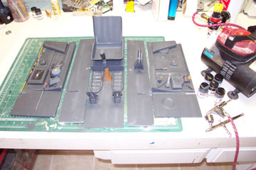
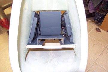
A wood framework is installed in the interior to hold the removable cockpit panels.
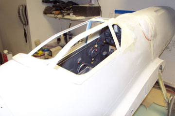
Cockpit with panels and floor installed.
Starting to look realistic. All the vacuum formed cockpit parts fit extremely well and are easy to detail.
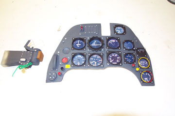
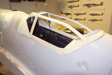
Instrument panel and gunsight. The cast resin instrument panel is ready to paint and saves alot of time.
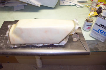
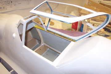
The canopy frame, which is vacuum formed plastic is a little too flimsy for my liking. Two layers of 2 oz cloth and west systems epoxy will make it less flexible.
The canopy frame is then sanded down and cut to fit the fuselage.
The cut lines are then drawn onto the frame using a 3 view as a reference.
The frame is then cut using a dremel with a cutoff wheel and then finish sanded by hand.
The cockpit panels are checked agian for fit with the framework.
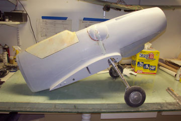
The front half of the canopy frame is then epoxied onto the fuse and blended in with evercoat.
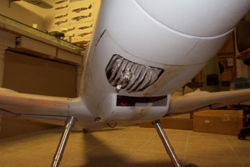
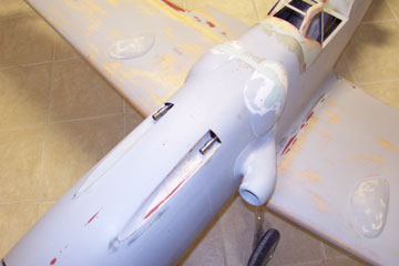
This shot shows how much the 3w75i will protrude from the cowl.
The use of the prop extension on the 3w allows the cylinder head to protrude from the hinged section of cowling only.
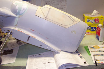
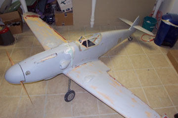
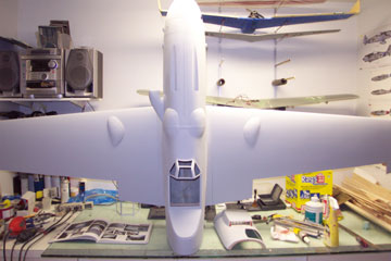
Motivational photo. Gotta put it all together every once in a while to see how it looks.
Mean looking front end.
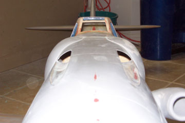
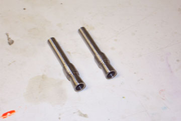
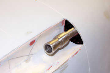
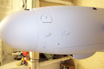
My father was kind enough to contribute to the project by machining some 1/4 scale MG131 gun barrels to protrude from the upper fuselage
The gun barrels are made from stainless steel.
Another shot of the gun barrels.
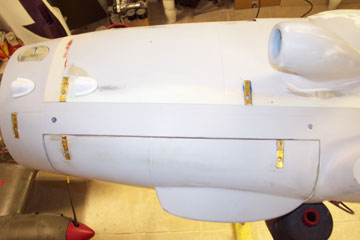
Simulated quick release latches are imbedded into the cowl.
The latches are made from 2 pieces of brass channel, and a machine screw head.
The latches are held in place with aeropoxy and then fiberglassed from the inside.
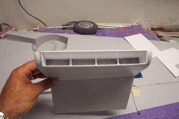
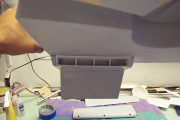
An entry for the oil cooler intake is created from styrene plastic and some aluminum tubing.
The fuse and wings are given another coat of K-36 in preparation of rivets and panel lines.
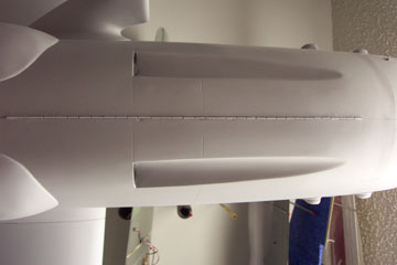
A simulated cowl hinge is made from sections of brass tubing with a small music wire on the inside and imbedded into the top of the fuse
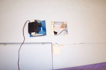
Aileron servo hatches constructed from 1/16th G-10. I also had to go back and insert some 1/8th ply for an aileron control horn mount.
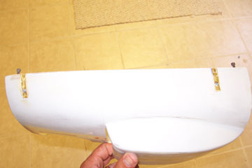
Left gear door cut to fit the wheel well.
Right gear door fitted.
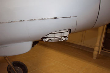
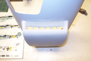
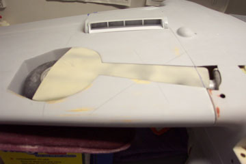
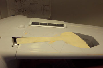
Radiator inlet made from .030 white plastic. I used a section of window screen to simulate the radiator itself.
Radiator attached to the bottom of the wing. The rear of the radiator acts as a wing flap in conjunction with the larger outboard flap.
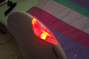
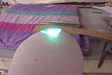
Port side nav light installed with lens and reflective tape in the enclosure
Starboard side nav light. These suckers are bright!
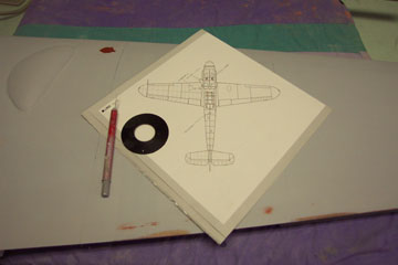
A 1/48th scale 3 view is used for wing panel
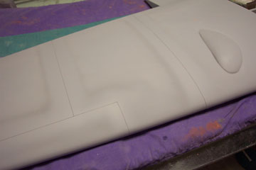
line placement. Panel lines are drawn on the wing in pencil, and then 1/64th chartpak tape is laid over the lines.
Several coats of primer are laid over the tape, the primer is sanded down to the tape and the tape is pulled off leaving a 3-d panel line.
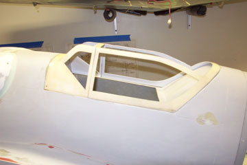
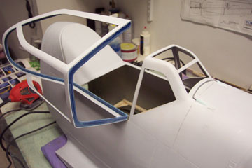
Work continues on the canopy frame. Canopy hinge used is a 5/8th nelson piano hinge.
The blue framing is 1/16th G-10 material to give the canopy frame some strength and to provide a base for the hinge and latch.