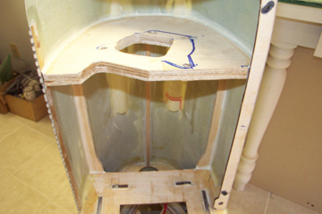
Firewall installed with BVM's Aeropoxy. 2 extra formers are added to each side along with one at the top to tie the firewall in with the landing gear formers.
The firewall is laminated from 2 identical pieces of 1/4 ply and is cut to clear the rear carb and the cylinder head.
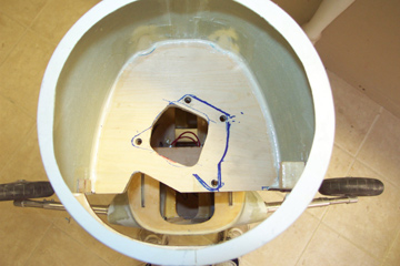
The firewall is then reinforced with carbon fiber tape and epoxy.
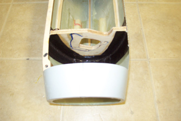
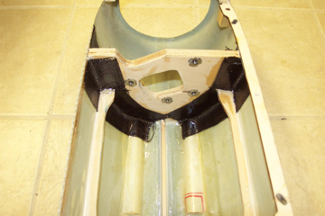
The rear of the firewall is given the same treatment.
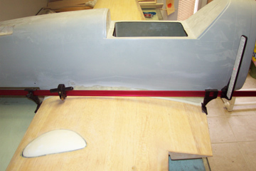
In preparation for installing the horizontal stabilizer, the front fuse and wings are blocked up on the table to read 1.5 deg positive incidence to establish a base measurement for the stab incidence.
A great planes lazer incidence meter makes this operation easy.
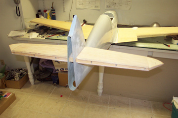
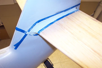
The rear fuselage half is then attached to the front with temporary screws and the stab location is cut out of the tail and the stab inserted thru the slot.
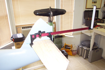
.The lazer meter is then attached to the stab and the angle adjusted until the stab measures ZERO degrees incidence relative to the wing.
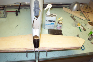
Initially the stab is held in place with CA. It is then attached with interior bracing and carbon fiber tape. Visible in the background is the epoxy from West System that I use for all laminating of fiberglass and carbon. The mixing pumps on top of the cans make mixing up a 1 oz batch of epoxy very easy and consistent.
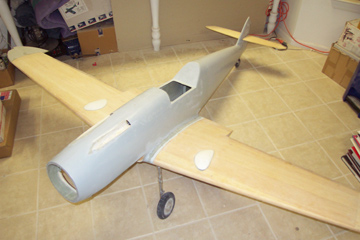
All thats left to construct is the rudder. Now its time to start adding all those scale details.
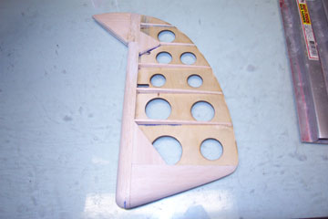
The rudder is built by attaching balsa blocks and ribs to the supplied 1/16th light ply core along with a generous amount of carving and sanding.
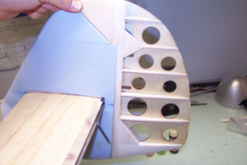
The rear of the fuselage forms the rudder shroud. The supplied core also has pre-cut lightening holes.
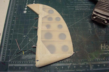
Rudder with control horn installed , hinge reliefs cut and covered with worldtex fabric covering.
Rear white navigation/anti-collision light installed in bottom edge of rudder. A small section of brass tubing is glued to the ply core and the light is mounted inside the tube.
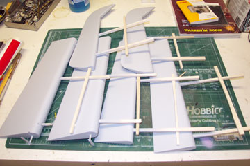
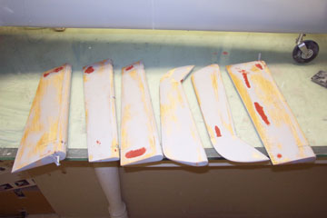
Elevators, ailerons and flaps primered with K36 automotive primer. Basa sticks are handles for holding the parts while painting and for hanging so they dont touch anything while wet.
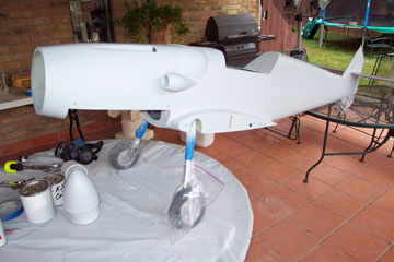
Spinner and wings with the first coat of K-36 auto primer. Now its time for some wet-sanding.
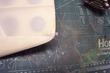
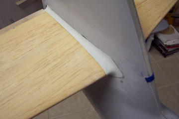
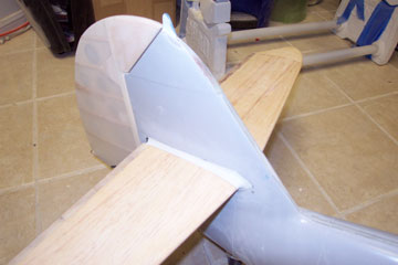
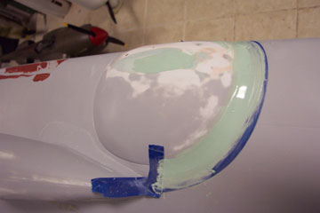
To simulate the stabilizer root cover of the full size, I put 3 layers of 3m fine line tape around the outline and made a fillet with evercoat
The evercoat is sanded down to the tape and the tape is then pulled off leaving a nice raised fillet.
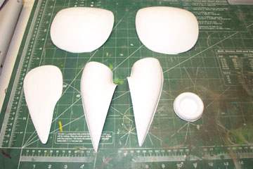
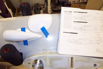
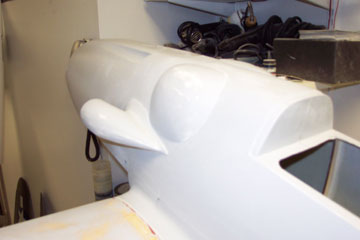
MG151 breech blisters and the 4 parts that make up the intake scoop. All parts are vacu-formed plastic and are very accurate in outline and shape.
G-6 side views in the Aero Detail book are used to determine the scoop and blister locatons.
No wonder the full size airplane was nicknamed "Buele" which means bump in German.
Radio antenna post is made from 1/16th G-10 and installed in the top of the fin.
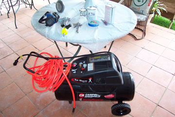
Compressor used for paint work is a Campell Hausfeld 15 gal 5 hp model that has very quiet operation. K-36 must be mixed with a hardener. Mixing ratios are available on the PPG website for primers, colors and clears.
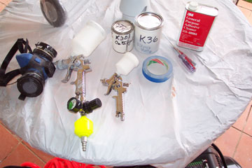
These are the items needed for applying K-36 and PPG DBU DCU basecoat/clearcoat. The larger HVLP gun is for primer only while the smaller model is for color and clear coats. The smaller model has a much finer spray pattern for camo work.
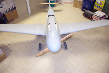
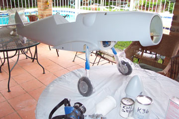
The gelcoated fuse is lightly sanded and the first light coat of K-36 is applied. All painting is done outdoors with plenty of ventilation.
Plastic ziplock bags are handy for masking landing gear and struts.
Flaps, Ailerons, and Elevators are primered with K-36, wet sanded with 320 grit and a sanding bock. Nitro Stans putty is used to fill small low spots and pinholes.
Bumps and blisters and scoops are given the same treatment.
Gun blister with evercoat added on the rear half to match characteristics of the the full size aircraft.
The evercoat is sanded down to the tape and then the tape is removed leaving a raised edge.
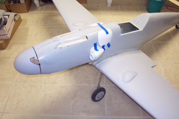
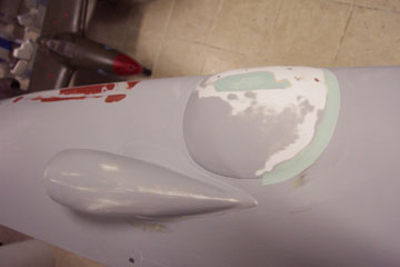
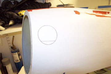
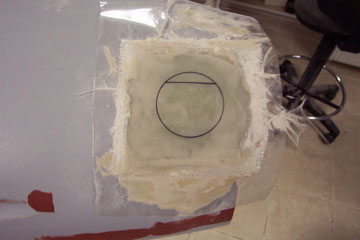
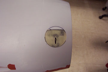
The oil filler hatch on the full size provides a great location for a hidden ignition switch. Here the outline is drawn on the fuse.
Clear monokote is then ironed onto the fuse over the hatch location.
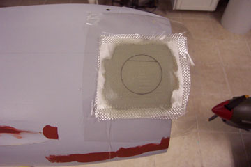
4 layers of 2 oz. cloth and 1 layer of 1oz cloth on top are laid up with west systems epoxy.
Once the epoxy cures, one more layer of microballoons and epoxy is applied to fill the weave and then the layup is finish sanded while still stuck to the fuse.
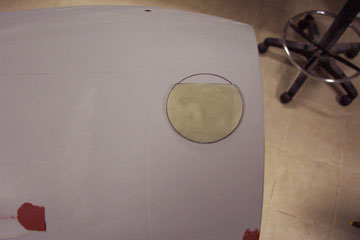
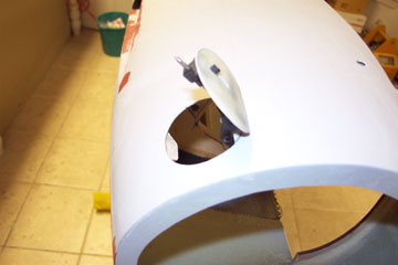
The hatch is then cut out of the layup.
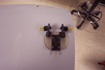
BVM offset hinges and hatch latch are then positioned on the hatch to check fitment and clearance.
Once everything fits right, the hinges and latch can be glued to the hatch and the matching hole cut into the fuse.
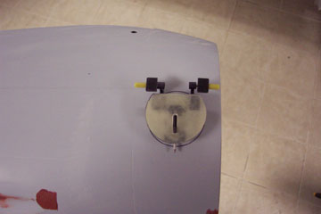
Fitment is checked again and then the hinges are glued to the inside of the fuse.
Next a back plate will be built to hold the switch inside the fuse and accessible thru the new hatch.
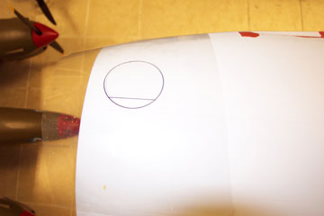
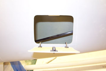
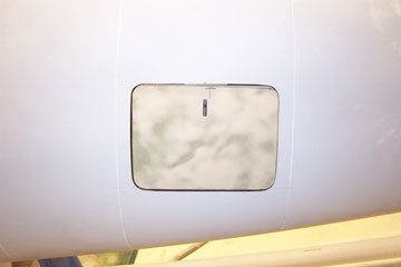
Another similar hatch is constructed for the rear of the fuse in the scale access location.
This hatch will conceal the radio switches and retract filler.
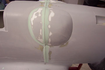
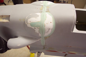
4 layers of 1/16th tape are applied to the fuse where the major cowl panel line is located and evercoat is applied over the tape.......
The putty is then sanded down until the tape shows and then the tape is removed to reveal a nice wide panel line.