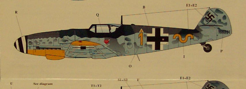
Every good model starts with the choice of a trim scheme. For the 109, I chose a profile that has good documentation. In this case, it is Bf-109 wk num. 166221
flown by Erich Hartmann. This is the aircraft in which he scored his 296-301st aerial vicories. Hartmann went on to become the highest scoring ace of all time with 352 aerial victories.
Although I had planned to build my thunderbolt next, When I saw this kit advertised, I knew I had to have one. I ordered my kit before the first production kits were ready way back in Sept 01. The kit finally arrived in Dec of 01 and It was definately worth the wait. Pat really did a good job on the instruction booklet as it is clear and easy to understand. The kit quality is outstanding with good quality hardware and an absolutely pin hole free gel coated fiberglass 2 piece fuselage. This should make it pretty easy to install all the formers and interior.
The wings are foam core with a built in balsa/ply/carbon fiber full length spar. They are also detachable from the fuselage and the scale landing gear stays with the fuse just like the real thing. The wings also utilize a very scale flap/radiator flap arrangement that has to be seen to believed. Hats off to
Pat Mc Curry of PCM models for taking the time to do the kit right. Go see his site to get all the facts on this awesome 109.
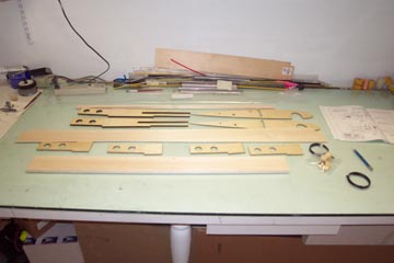
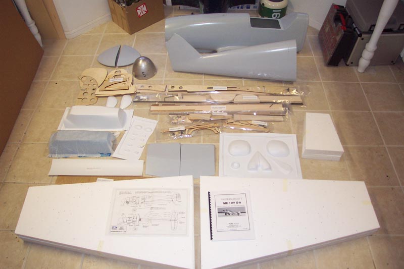
Kit Contents
The first step in construction of the 109 is to lay out the pieces needed to build the wing spars. Here are the balsa, lazer cut plywood and carbon fiber components of the wing spars.
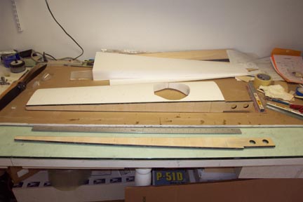
Here are the wing spars built and one has been attached to the front foam wing core.
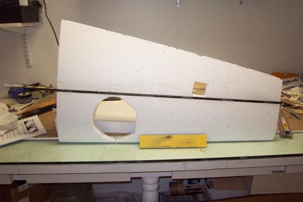
Here is the right wing with the aileron servo well cut out, spar epoxied to front and rear wing cores and ready for sheeting. The wings with the spars installed are incredibly strong. They should be even stronger once the sheeting is installed. I placed the wing tip on the table and held the spar end and I could not bend the wing at all.
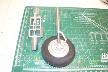
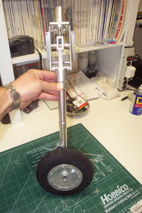
Here are the scale retracts that are available for the 109 kit. They are extremely well built and very solid. I'm holding one so one can get an idea just how big they really are. The 6" wheels are from glennis and they are for my 1/4 scale FW190d9. I plan to contact glennis for another set for the Bf-109.
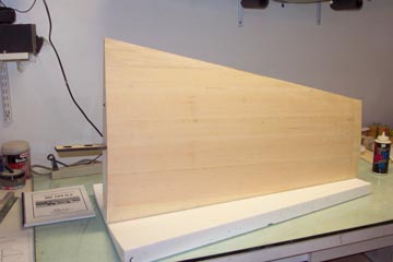
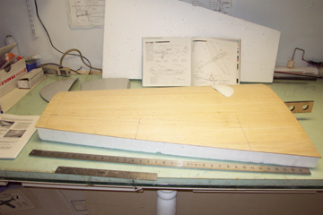
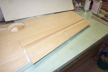
Left wing panel, fully sheeted with
1/8th balsa. One thing I added was a 1/2" strip of 1/64th ply between the top and bottom sheeting at the trailing edge. The ply is glued in with the grain running chordwise to the wing. When sanded down to a feather edge, this leaves a VERY strong trailing edge. Hopefully this will minimize hangar rash. Pat Mc Curry supplied this tip in an article he wrote for RCReport.
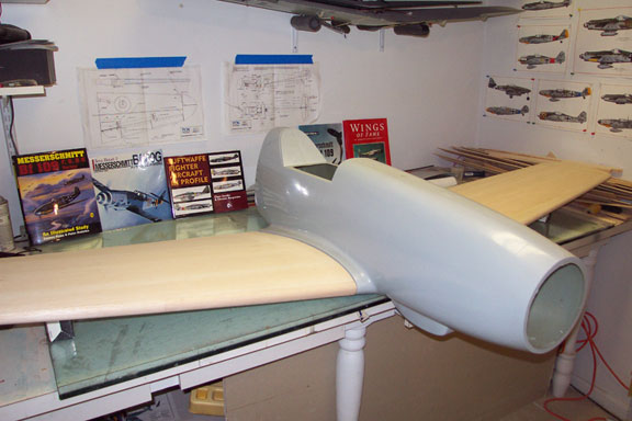
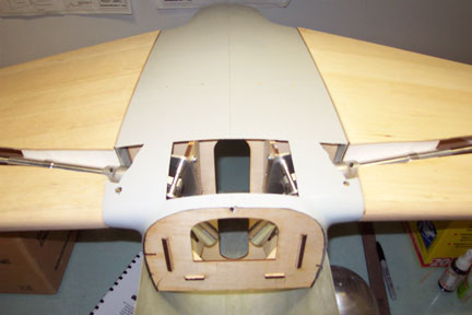
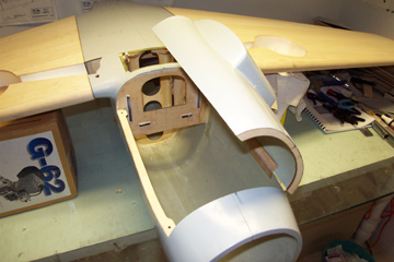
Work has finally started on the 109 again. Both wings are now sheeted with leading edges attached and are in the process of being fitted to the fuselage. There are 2 interior formers that capture the 2 wing spar stubs that protrude into the fuse. As you can see, this bird is quite a bit larger than my other planes. The fuselage being in 2 pieces at this point makes things easier.
In the background are some of the documentaion books I will be using to get all the detail correct.
Progress is continued on page 2
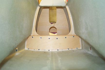
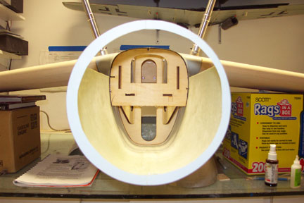
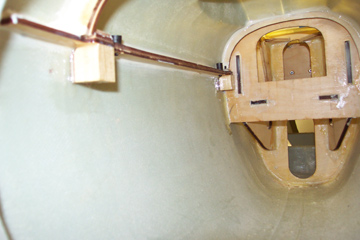
Looking from the rear of the fuselage towards the front, you can see the spar support epoxied into the fuselage. Wood formers are tacked in place with thick CA , then a bead of BVM's aeropoxy is put around all contact points. The bead is then smoothed out with a finger to get a nice fillet.
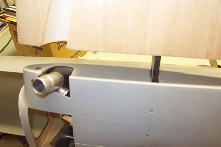
This shot shows how the spars slide into the fuselage. There are 2 set screws for each spar stub and a 6-32 bolt just behind the leading edge that is captured by a cam bolt inside the fuse, to hold the wing on. There is also a carbon fiber locator pin behind the spar to keep the wing from rotating.
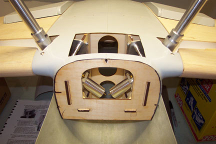
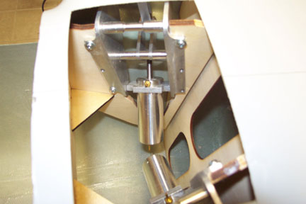
Landing gear former installation. The formers have been tack glued in with CA to make sure everything fits and the gear has the correct angle while it is extended......
and retracted. Notice that the air clylinders have moved farther apart when the gear is retacted.
Looking from the front of the fuselage, the landing gear formers tack glued into position. All wood/wood and wood/fiberglass joints will be attached with Aeropoxy. Also, the areas around the gear will be fiberglassed with 2oz cloth for strength.
landing gear mechanisms and formers.
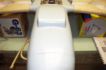
Next step is to mount the hinged cowling. The kit is designed so that the cowl opens the same as the full size airplane. Here is the uncut cowl.
Cowl cut out from the fuselage and formers installed. Clamps are holding the continuous hinge as the epoxy cures.
Cowling hinged to fuse with all formers installed.
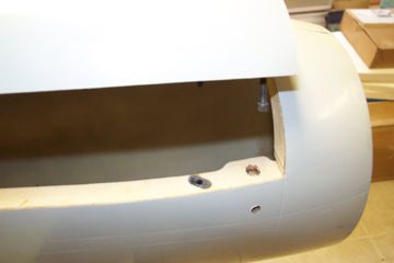
Visible here is the camlock that captures the 6-32 bolt that protrudes from the cowl. The black oval is the receptacle for a carbon fiber locator pin which is installed in the movable cowl.
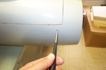
A simple twist of the screwdriver secures the cowl to the fuse.
This shot shows the camlock blocks inside the fuse. The firewall, engine, fuel tank and other components will go in here.
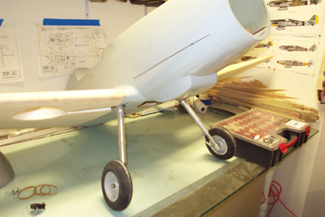
Sitting on her landing gear for the first time.
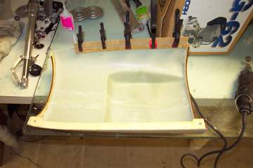
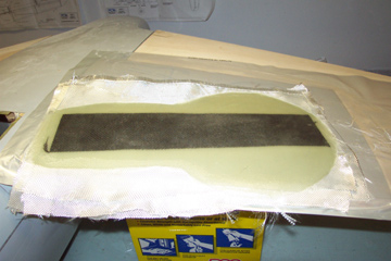
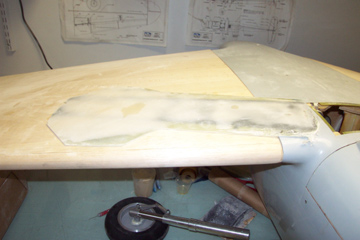
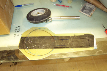
Landing gear doors being laid up. First, 1/64th ply was taped onto the wing structure so that the glass cloth would not fall into the hole for the landing gear. Next monokote was ironed onto the ply and the wing. The 7 layers of 2 oz cloth were then applied with one strip of carbon fiber in the middle for strength.
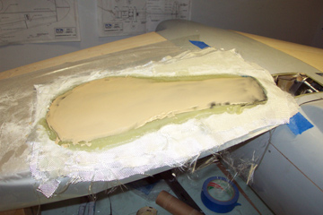
After sanding, one more layer of epoxy and microballons is added ....
And then sanded smooth. The gear door is then rough cut out of the layup. Final shaping will be done when the wheel bays are finished.
Looking at the bottom of the new gear door layup. The black line shows what I thought the door shape would be. The blue outline shows the actual size and shape. This is why I cut it out of the layup oversize.
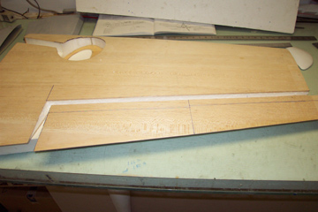
Left wing marked for the cutting out of the aileron and flap.
Aileron and flap cut out fo the trailing edge as one unit.
1/4 balsa is added to the trailing edge of the wing and 1/2 balsa is added to the aileron and flap to form the leading edge of each.